Many people grew up with older consoles and handhelds such as the Game Boy or the SNES. These retro consoles had a limited colour palette, and the art direction of gamed made for these systems reflected the restrictions placed upon artists. Recently, there has been a revival of classic consoles such as these, with Nintendo cashing in on their fans’ nostalgia with the NES and SNES Classic - today, we are going to use Shader Graph to replicate the unique colour palette restrictions of these consoles, starting with the original Game Boy.
Game Boy Effect
The original Game Boy could only display four colours, each one a different shade of green. The easiest way for us to make a shader to automatically transform an object to Game Boy colours would be to calculate the luminance of each pixel, then match that up to the four colours, from darkest to lightest. So that’s what we’re going to do! There are two main ways of doing this, so we’ll do both.
Property-driven Version
For the first method, start by creating a new Unlit Graph by going to the Project View and selecting Create -> Shader -> Unlit Graph, and name it “GameBoy”. We are going to write a shader which takes lighting into account, but we don’t want Unity to automatically apply lighting, so we won’t be using a PBR Graph.
We’ll begin by adding the properties for this shader. We’ll need a Main Texture, of type Texture2D - this will control the base colour of the object before the Game Boy colour transformation is applied. After that, we’ll need to add four Color properties for each of the Game Boy’s four colours. I’m going to name them Darkest, Dark, Light and Lightest, and give them each a default value based on the Game Boy’s original colour palette, with hex values #0F380F, #306130, #8AAB0F, and #BBCF5D respectively. Finally, we will add a keyword to control whether to take lighting into account. That way, you can toggle between enabling and disabling lighting using a checkbox on the material Inspector. Go to Keyword -> Boolean, and name it something descriptive Use Lighting?, with a reference value of USE_LIGHTING_ON. The _ON needs to be there to make the keyword toggleable in the Inspector.
 Hippity hoppity, here are my properties.
We want to modify lighting information inside Shader Graph, but unfortunately there’s not yet a node that lets us access it. Fortunately, we can write our own custom nodes using shader code. This section is based on an excellent article by Alex Lindman on the Unity Blog site, so if you’re not interested in code you can just copy the required code from her article under the “Using the Custom Function File Mode” subheading and skip ahead in the article.
Start by creating a new file. We’re going to write a single function, with a void return type, called MainLight_half; the half is important because this tells Unity the precision to expect this function to use. We’ll see later that we can override the precision used, so if we wanted to, we could write another function called MainLight_float, but we won’t worry about that here. This function is going to output diffuse lighting information from a single light, but you can include specular light and additional point lights if you follow the rest of the article.
This function’s parameters are a float3 called WorldPos - this will be the world position of a pixel; an out half3 called Direction, which lets us output the light’s direction to our shader graph; an out half3 called Color to denote the light colour; and finally two half parameters called DistanceAtten and ShadowAtten, to output the light attenuation due to distance and presence of shadows respectively. Attenuation just means that the light strength has a smooth falloff over distance and in shadow.
void MainLight_half(float3 WorldPos, out half3 Direction, out half3 Color,
    out half DistanceAtten, out half ShadowAtten)
{

}
When this code is running on an object in Shader Graph, we need to create a fake light to make sure the preview windows are rendered properly. Use the #if SHADERGRAPH_PREVIEW directive to check if we’re inside a preview window, and if so, create some default values for each of the four output variables.
#if SHADERGRAPH_PREVIEW
    Direction = half3(0.5, 0.5, 0);
    Color = 1;
    DistanceAtten = 1;
    ShadowAtten = 1;
#else

#endif
Else, the code is likely running in the Scene or Game view so it should be able to find a real light to work with. Between the #else and #endif, we’ll need to use #if SHADOWS_SCREEN because some types of light apply shadow maps in screenspace. In that case, we can first transform the WorldPos we passed into the function from world space to clip space using the TransformWorldToHClip function, then convert it to a shadow coordinate using ComputeScreenPos. Otherwise, if SHADOWS_SCREEN is not defined, that means shadows are calculated on the object’s geometry instead, so we can just use TransformWorldToShadowCoord.
#if SHADOWS_SCREEN
    half4 clipPos = TransformWorldToHClip(WorldPos);
    half4 shadowCoord = ComputeScreenPos(clipPos);
#else
    half4 shadowCoord = TransformWorldToShadowCoord(WorldPos);
#endif
Once we’ve got the shadow coordinates, we can grab the main light using GetMainLight, making sure we pass in shadowCoord to get the correct shadow attenuation for our pixel’s world position. The light gives us direct access to each of the four output variables, so just set each of them in turn and then the script is complete. Save it somewhere sensible as an HLSL file - I called mine “Lighting.hlsl”.
    Light mainLight = GetMainLight(shadowCoord);
    Direction = mainLight.direction;
    Color = mainLight.color;
    DistanceAtten = mainLight.distanceAttenuation;
    ShadowAtten = mainLight.shadowAttenuation;
Here is the full code if you just want to copy it all over at once:
void MainLight_half(float3 WorldPos, out half3 Direction, out half3 Color,
    out half DistanceAtten, out half ShadowAtten)
{
#if SHADERGRAPH_PREVIEW
    Direction = half3(0.5, 0.5, 0);
    Color = 1;
    DistanceAtten = 1;
    ShadowAtten = 1;
#else
#if SHADOWS_SCREEN
    half4 clipPos = TransformWorldToHClip(WorldPos);
    half4 shadowCoord = ComputeScreenPos(clipPos);
#else
    half4 shadowCoord = TransformWorldToShadowCoord(WorldPos);
#endif
    Light mainLight = GetMainLight(shadowCoord);
    Direction = mainLight.direction;
    Color = mainLight.color;
    DistanceAtten = mainLight.distanceAttenuation;
    ShadowAtten = mainLight.shadowAttenuation;
#endif
}
Return to the GameBoy shader graph and create a new Custom Function node. By clicking the cog menu, we can insert custom shader code into this node and modify the inputs and outputs to the node to match the parameters of the function we just wrote. Go ahead and add a single input called WorldPos, of type Vector3, then four outputs called Direction, Color, DistanceAtten and ShadownAtten, of types Vector3, Vector3, Vector1 and Vector1 respectively. We’ll need to type the name of the function in the Name field, but leave out the _half and just type MainLight, then attach the Lighting.hlsl file we just wrote to the Source field. Finally, we need to set the precision at the top to Half, and your node should turn an off-green colour. If you had created an alternative function called MainLight_float, this is where you would pick between them.
Now we can create a new Position node in World space and hook that up to the WorldPos input on the Custom Function node. Now that we can access diffuse lighting information, we need to apply that to our mesh by using the dot product between the Normal Vector of the mesh and the direction of the light. On the preview, you’ll see it shows us a lit sphere as intended. Use a Saturate node to make sure the values are bound between 0 and 1, then we’ll apply ShadowAtten, DistanceAtten and Color by multiplying them all together using two new Multiply nodes, then finally use another Multiply node to tie everything together. I’m also going to go one step further and Add the scene’s Ambient Light. We can output this all to the Color pin on the Unlit Master node to see the final preview of what the lighting looks like.
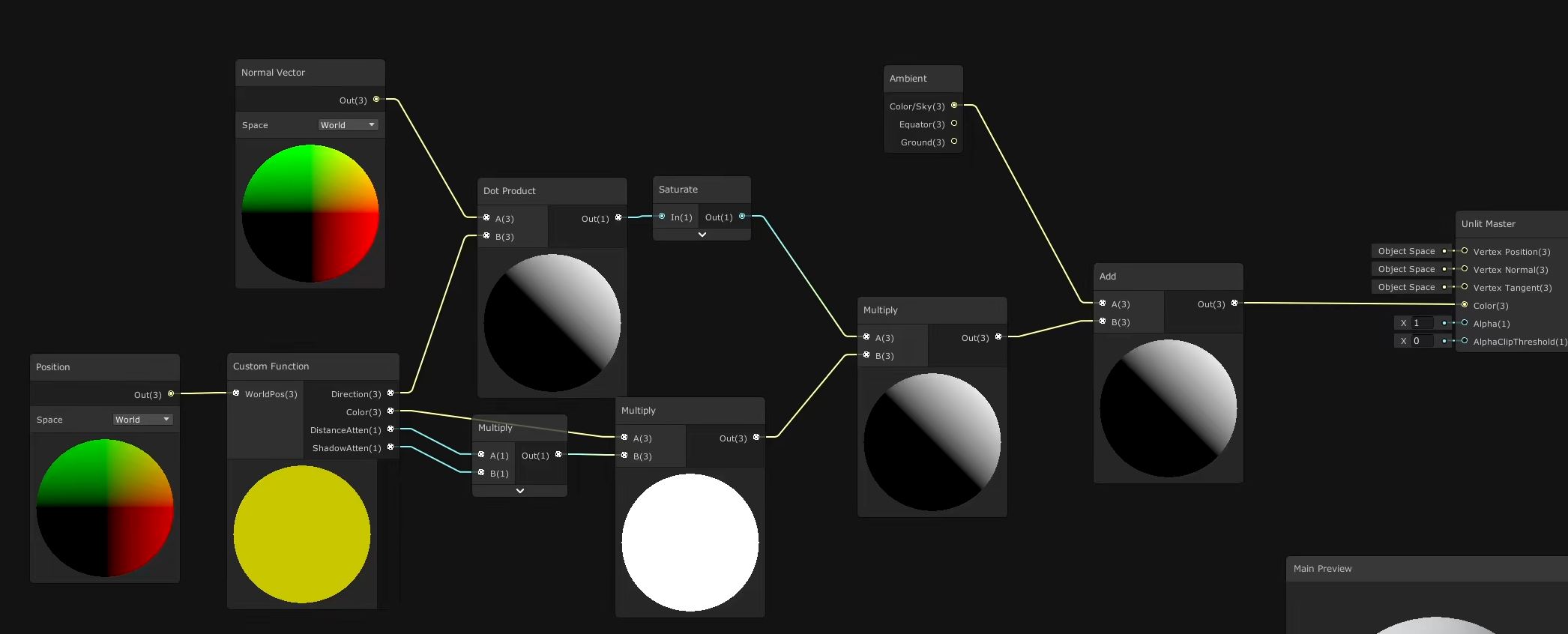 In which we make sure things are appropriately #lit.
There’s still a way to go with the Game Boy shader, and all this lighting code is going to be needed later on in other shader graphs. Rather than copy-pasting this entire network of nodes, we can select all of them except the Master node, right-click and select Convert to Sub Graph. A sub graph allows us to wrap a group of nodes together and then use them in additional shader graphs as if they are a single node. We’ll name this sub graph something along the lines of “GetLighting”, and the GameBoy graph will update accordingly to show only a GetLighting node feeding into the Color pin. If we look at the GetLighting graph, all the nodes are connected in the same way - the only exception is that there’s a new Output node. We can rename it by going to the cog menu, double-clicking the name of the output - let’s call it something like “Light”. If we go back to the GameBoy graph, the name will update accordingly.
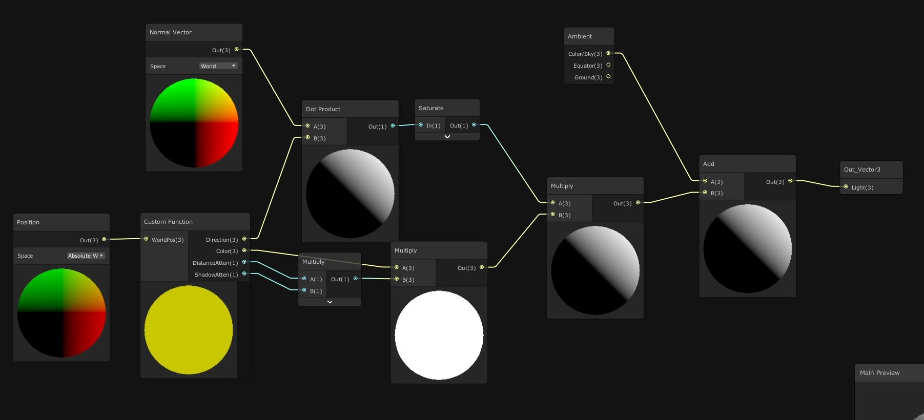 A subgraph only works as part of the collective, #communism.
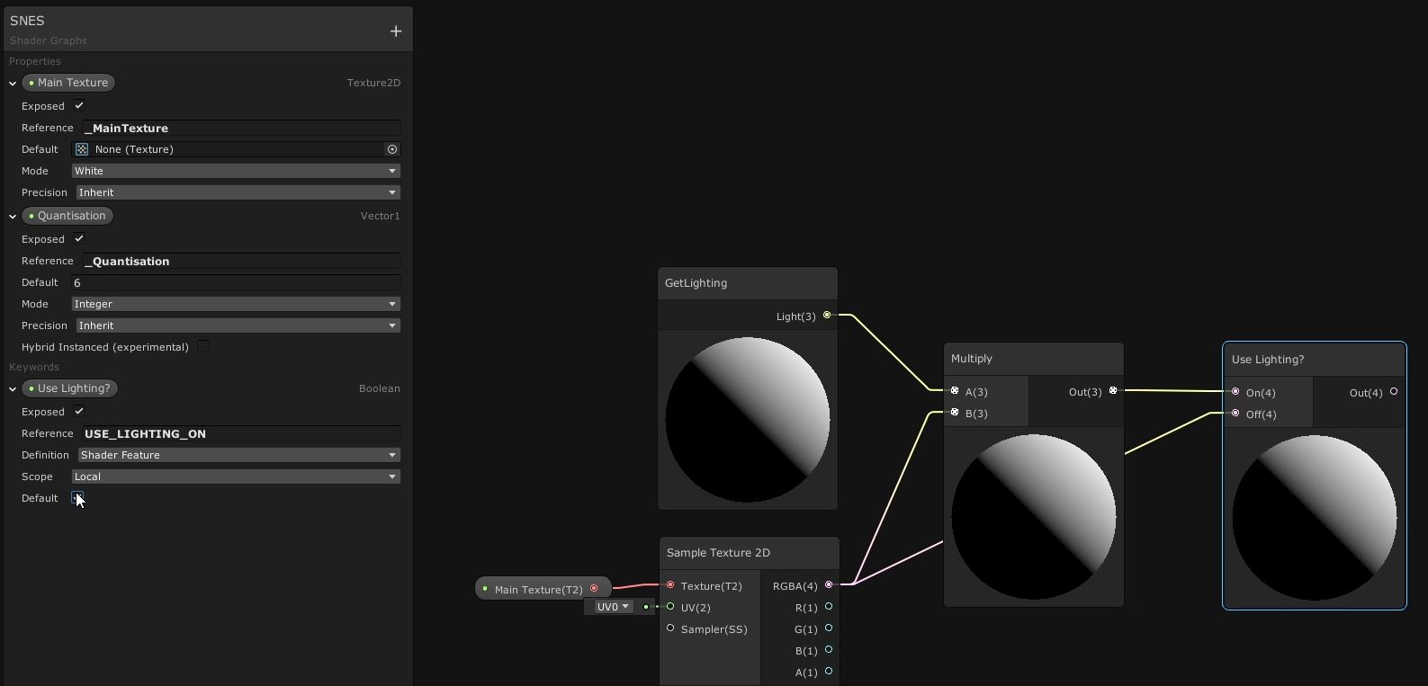
Now we can apply the lighting to the model. Drag the Main Texture onto the graph and use a Sample Texture 2D node to grab the albedo colour for this object. If we then Multiply by the light value from GetLighting, it’ll apply the lighting to our base texture. However, we also included Use Lighting as an optional keyword, so we’ll need to use that keyword’s node to tell Unity which values to use when lighting is on or off. Pass the result of the Multiply into the On slot, and then pass the RGBA output of the Sample Texture 2D node to the Off slot. Now, the output of the Use Lighting keyword node gives us a lit or unlit texture based on whether Use Lighting is ticked.
 The Shader Graph equivalent of a light switch.
Next, we need to determine the luminance, or brightness, of the pixel. We can do that by doing the Dot Product of the pixel’s color with a new Vector3 with values (0.2126, 0.7152, 0.0722). You won’t see a difference immediately because our default texture is already greyscale, so if we mess with the Main Texture value, we will see a change between the previews on Use Lighting and Dot Product.
 This part of the graph is particularly illuminating.
Finally, we will determine which Game Boy green colour to use based on the luminance value. We can do this using a Comparison node, which compares the A and B values based on the comparison type specified on the drop-down menu. We’re going to check if the pixel luminance is greater than 0.75, which we pass into a Branch node’s Predicate field. For its True output, pass in the Lightest property - in effect, we’re saying “if the luminance is greater than 0.75, then output the lightest green”. We’ll need to pass something into the False slot. For that, create another Comparison node to check if the luminance is greater than 0.5. The result gets output to another Branch node, with the Light property slotted into the True field. The output of that Branch node will be output to the False field of the previous Branch node.
Finally, to factor in the final two colors, create a third Comparison node to check if the luminance is greater than 0.25. Output that to a third new Branch node and slot the Dark property into the True field, and the Darkest property into the False field. The output of the third Branch can be input to the second Branch node’s False field. We can play around with different textures to instantly see different results on the preview windows. Finally, output the first Branch node to the Color field on Unlit Master to complete the GameBoy shader.
 Pretty straightforward, compared to other methods.
Ramp-controlled Version
As I mentioned, I want to show you two ways of achieving a Game Boy effect, so I’ve duplicated the Game Boy shader graph and named the new one “GameBoyRamp” - you’ll see why it’s named that shortly. Go to the end of the graph and delete the group of Comparison and Branch nodes after we calculate the luminance. Also, for this second technique, we don’t need the four Color properties, so also delete these.
In their place, add a new Texture2D called Ramp Texture. A ramp texture lets us encode a gradient of colours to use within a shader - in this case, I’ve created a texture which contains the four Game Boy colours, each taking up a quarter of the texture’s width. If you’d like to use this texture, it’s contained in the GitHub repository for this project. I’ve set that as the default value for this property. I also add a SamplerState property called Ramp Sampler State. A Sampler State is a collection of settings used to sample a texture - using one of these, we can override the filter mode and wrap mode of a texture and ignore the settings used in the texture import window. We want to change the Wrap Mode to Clamp to avoid glitches where the luminance calculation equals exactly one or exactly zero, because if it is set to Repeat then Unity will blend together the two colours at the far ends of the ramp texture.
 Swiggity swooty, here’s some properties again.
Use a Saturate node to ensure the luminance is clamped between 0 and 1, then create a brand new Vector2, using the luminance as the x-component. Set the y-component to 0.5, then use this Vector2 as a UV coordinate to sample the Ramp Texture using a Sample Texture 2D node. Remember to connect the Ramp Sampler State to the Sampler field, and finally output the sample to the Color field on Unlit Master to complete this shader. The difference between both approaches is subtle, but you’ll notice that edges tend to be softer using the texture ramp method.
 This graph is ample when the ramp is sampled.
It’s down to preference which approach you take, but each has advantages: the property-driven version gives you full control within the material inspector to change the colour values however you’d like, but the ramp texture approach supports an arbitrary colour ramp, so you can encode more than 4 colours at whatever luminance thresholds you’d like.
Now that we’ve completed the Game Boy shader, we’ll move on to a SNES-style shader.
SNES Effect
For this effect, we’re not going to accurately emulate how the SNES handles colour exactly, because it’s actually pretty complicated - it can display 256 colours at a time out of a total of 32768. Programming that restriction in a shader would be extremely cumbersome. Instead, we’re going to quantise the colours so that each colour channel only has a limited range of values.
Let’s start by creating another new Unlit Graph called “SNES”. Add a Main Texture property of type Texture2D, then add a new Vector1 property called Quantisation, with a default value of around 6. It’s important that we set the Mode to Integer for this property. We’ll also need to add a Use Lighting keyword like we did for the Game Boy shader - give it the same name and reference as before. We’ll set up the lighting the same way as before, so add a Get Lighting node. Read the Main Texture using a Sample Texture 2D node, and Multiply the two together. To pick between enabling and disabling the lighting, add a Use Lighting keyword node and connect the Multiply node to the On field, and the RGBA from the Sample Texture node to the Off field.
 I’ve run out of puns to do with the word “property”.
We’re going to perform the quantisation calculations on each colour channel in turn, so use a Split node to separate each colour channel. We’re going to Subtract a small epsilon value so that the colour channel value never quite reaches 1, then Multiply by the Quantisation value. After that, we’ll use a Floor node to truncate the value to an integer. The next step is optional - if we Add 0.5, then the final output ends up looking a bit less dark and oversaturated, but feel free to leave this node out if you want. Finally, we need to divide by Quantisation minus 1 to get our values in the correct range, so drag a Divide node off the Add node, then take the Quantisation property, Subtract 1 from it, and pass that to the other pin on the Divide node. Remember that we’re building a new color, so output this into new Vector3 node in its first input pin. Connect that to the Color pin on Unlit Master, and you should see the main preview change to red.
 Quantisation is like turning a smooth curve into steps.
We could just copy and paste this for each color channel, but earlier we saw that sub graphs are great for reusing code, so select everything in between the Split and Vector3 nodes, right-click and Convert to Sub Graph. Name this something along the lines of “Quantise”. You’ll see that, as before, it’s replaced everything with a new node, but it’s messed up slightly and takes two Quantisation inputs when it just needs to take one. We can quickly find the sub-graph by right-clicking the node and selecting Open Sub Graph. On the left-hand side, the properties are the inputs to this sub graph. We don’t need two versions of Quantisation, so go ahead and delete one of them, then drag the existing Quantisation property and plug it into the slot where the duplicate got deleted. I also think the Vector1 input can be more descriptive - it’s meant to represent a color channel value, so rename it “Color”. Similarly, go and change the output’s name to “OutColor”.
 Cleaning up the Quantisation code.
Back on the SNES graph, connect the Quantisation property to the Quantisation pin, then copy and paste the pair of nodes a couple of times. Connect the G and B components of the Split node to the new Quantise nodes, then feed their outputs to the Y and Z components of the Vector3 respectively to complete the shader.
 Channel-by-channel quantisation.
We can play around with different textures and toggle the lighting to see the difference it makes to the output. The same goes for the Game Boy shader - the difference between lit and unlit is interesting. Furthermore, if we want to make this look more like the NES, with its far more restrictive colour space, we can just tone down the Quantisation level. See if you can integrate more interesting lighting using the remainder of Alex’s tutorial.
Conclusion
We’ve used a variety of techniques to recreate the retro feel of classic consoles using Shader Graph. Sometimes, it’s not necessary to emulate the exact technical specifications of those consoles’ displays - an approximation will evoke the same nostalgia from fans. We also have more creative control if we give ourselves a bit of wiggle room. If you really wanted to sell this effect, I’d recommend pixelating the image, although creating custom image effects in URP is a bit technical and might put some people off.
Next Time
For the next shader tutorial, I’m going to deconstruct the Octocamo mechanic in Metal Gear Solid 4: Guns of the Patriots. We’ll write the shader to change Snake’s comouflage seamlessly between two different textures, and we’ll use code to detect the texture on the floor or wall he is leaning or crawling on, whether it’s a MeshRenderer for the wall or a Unity terrain for the floor. It’s my first time using Unity’s newer terrain system, so I’m excited to put the effect together! Until next time, keep on making shaders!