Recently, rendering in Unity has been totally revolutionised by the addition of Scriptable Render Pipelines - in short, SRP lets developers completely control how Unity renders a scene. While it’s possible to roll your own custom renderer, there are two presets which most people will probably use - High Definition Render Pipeline (HDRP), which targets high-end consoles and PC, and Universal Render Pipeline (URP, previously known as Lightweight Render Pipeline, LWRP), which is designed to scale across a broad range of devices, including mobile platforms. SRP also brings support for Shader Graph, Unity’s new node-based shader editor. We’ve been using the old basic renderer so far on this website - today, we’re going to leave it behind and build a brand new cel-shader in URP and Shader Graph!
Shader Graph
In this section, we’ll introduce what Shader Graph is, how to create new graphs, and how they relate to the traditional shader code we’ve been writing so far.
Shader Graph is Unity’s new-ish node-based shader editor. Instead of writing code, most of your time will be spent moving around pre-programmed nodes - which do simple tasks like add two vectors, sample a texture or step between two values - and connecting the outputs of one node to the inputs of other nodes. If you’ve used Unreal Engine or even Blender, you may have come across similar node-based systems already.
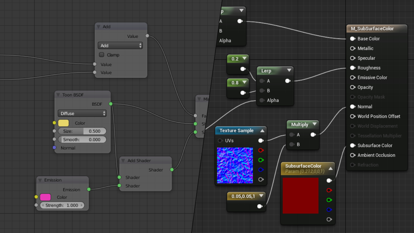 Node editors in Blender (left) and Unreal Engine (right).
There are several benefits of this approach over conventional shader code. Obviously, it’s more approachable to non-programmers. Each node has clearly labelled inputs and outputs so it’s a lot easier to get to grips with than code. On top of that, much of the boilerplate code required when writing shaders is removed - graphs tend to only include directly relevant information. All of this is not to say code is redundant - it’s still possible to write custom nodes using shader code (which we’ll do in this tutorial).
The other main benefit to using Shader Graph is that certain types of node generate a preview window which show what the material looks like so far - you can use those to debug what the shader is doing more immediately than you can using code. That’s not the only thing that’s visualised - use a Color node, and Unity will display the colour. Use a Sample Texture 2D node, and the texture will pop up in a little window. You can minimise most of these previews to keep the graph concise, but it’s extremely useful to see what your material looks like at key stages.
For this tutorial, we’ll be using a handful of the nodes and features of Shader Graph which should give you a good grasp on how Shader Graph differs from code, or - if you’ve never written shaders before - be a solid base to start writing your own shaders!
Shader Graph Basics
Let’s create our first graph. First, make sure you’re using Universal Render Pipeline in your project - either select the URP template when creating the project or find it in the Package Manager (Window->Package Manager) - it’s listed as “Universal RP”. Right-click in the Project window and under Create->Shader there will be a handful of graph presets:
2D Renderer: containsLitandUnlitgraph presets for sprite renderers. As of Unity 2019.3, which I’m using, these are listed as experimental.Unlit Graph: for materials which won’t need to use lighting.PBR Graph: stands for “physically based rendering”, which means the material will using the lighting engine.VFX Shader Graph: stands for “visual effects” and can be used to render large-scale particle effects on the GPU.Sub Graph: acts a bit like a function - you can bundle together common sets of nodes into a sub graph, then use the sub graph as a node in a main graph.
In this tutorial, we’ll be using PBR Graph. Once you’ve created a graph, name it whatever you want then double-click it to open up the Shader Graph editor tab - you should see a single node called PBR Master.
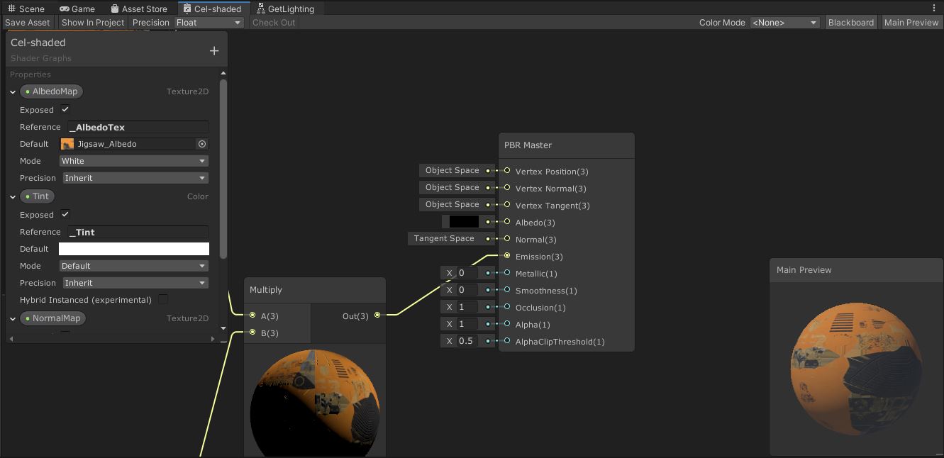 An example Shader Graph.
Let’s run through the Shader Graph editor layout. The Blackboard - by default in the top-left corner - contains a list of properties and keywords. Properties are like inputs - these can be exposed in a material and freely tweaked outside the shader. Keywords allow you to define multiple shader variants and strip away unneeded code - we won’t use any of those in this tutorial. You can toggle the Blackboard on and off using the button in the top-right of the window.
In the bottom-right by default is the Main Preview, which displays a live-updating preview of what your material looks like (according to the default property values set in the Blackboard). You can right-click on the preview window to swap the shape of the preview mesh to a cube, quad, sphere and a handful of others. The toggle button for Main Preview is also in the top-right of the window.
Finally, your PBR Master node sits in the centre. For each graph type, a different master node is placed on the graph - PBR Master is the corresponding master node for a PBR Graph. If you’ve used Unity’s Standard Shader (from Unity 5 onwards), the inputs to this node will look familiar: rather than defining the output based on what colour a pixel is, we define what the albedo (base) colour is, then configure what the physical properties of the surface are: how metallic and smooth it is, how much light is emitted by portions of the object, and so on. Unity then applies lighting to the object based on these properties. The Unlit Master node contains everything that PBR Master does except those physical properties.
The best way to get to grips with Shader Graph is to start using it, so let’s jump right in! You can download the project files from GitHub or create the graph from scratch.
Cel-shading in Shader Graph
We’re going to create a cel-shading effect using Shader Graph, aiming for a result that looks like the lighting used in The Legend of Zelda: Breath of the Wild or The Wind Waker. There’s a lot of moving parts to this, so we’re going to walk through each step as completely as possible - hopefully you’ll have no questions left unanswered at the end! We’ll be building on other tutorials, which I’ll be linking throughout the article.
The first question we’ll ask is: why are we using the PBR Master node instead of Unlit Master? We’re writing a cel-shader, so we need to interact with Unity’s lighting engine. By default, an Unlit shader does not apply any lighting to the final material automatically - leaving us free to write our own lighting model - whereas PBR does apply lighting. However, that also means Unlit materials don’t receive shadows by default. There’s a trick we can use with PBR graphs to get the best of both worlds, courtesy of this tutorial. If we set the Albedo colour to black and the Metallic and Smoothness values to 0, Unity will strip out some of the lighting-related code from the compiled shader code. Then, we can plug in the colour we want to use for the material into the Emission channel. Unity will still apply the shadow to the material, but it won’t calculate any other lighting on the material.
Set the Albedo to black and Metallic and Smoothness both to 0 by modifying the values on the small tabs connected to those inputs. Then, left-click the tiny circle next to the Emission channel (this is called a pin) and drag out a line to the left. The Create Node dialog will appear (you can also open this with right click->Create Node) - either type in the word “color” and select the Color node or navigate to Input->Basic->Color using the menus. For this tutorial, I’ll just mention the name of the required node rather than list its location in the list from now on. We should now have an input to the Emission channel (if not, drag a line between the Color’s Out output to the PBR Emission input) - if we change the colour on this node to red, the Main Preview will change to red.
 Dragging out a new node from a pin will automatically connect the two pins.
Let’s use this in a real scene. I’m using the default URP sample scene for this, but I’ve made the drywall panel black, so we’ll be able to see lighting details more easily. Create a new material and select the graph we just wrote using the Shader drop down menu - you’ll find it under the Shader Graphs submenu - then attach the material to a sphere to see it turn whatever colour you defined on the graph.
 An unlit red sphere.
This is a good start, but you can’t modify the colour without going into the graph. Ideally, we would have a way of changing the colour on the material directly - for that, we can use Properties.
Properties and Texture Sampling
You’ll be familiar with Properties if you’ve written traditional shaders before. In Shader Graph, you can find a list of properties on the Blackboard. We’re going to add a new one using the plus symbol - select Color from the drop-down menu. We can rename these properties, so I’ve chosen to call mine “Tint”. We have plenty of other options too: Exposed lets you choose whether the property should appear on the material Inspector (which we want, so leave it ticked); Reference provides a name we can use to refer to this property through scripting - I’ve called mine “_Tint”; Default lets us set a default value; Mode allows us to choose whether the colour can use HDR - we’ll set it to HDR for later; and Precision sets which underlying datatype is used to represent this property in the compiled code - it’s easiest to leave this as “Inherit” for now.
We can use this property by dragging the name onto the graph, or by using the Create Node menu and searching for Property: Tint. All properties can be searched using their name and will be distinguished from other nodes with the same name with the “Property:” prefix. We’ll replace the existing Color node (you can delete it by right-clicking and selecting Delete) and plug this new Tint property node into the Emission pin.
 Properties let us expose variables to the material Inspector and scripts.
Let’s also add the ability to add a texture to the material. We will use a cel-shading technique for the lighting, but that doesn’t mean we can’t apply a base texture if we want! If we use Create Node to search for the word “Texture”, we get several options popping up - we’ll use the Sample Texture 2D node for this. We’ll also add a second property with the Texture2D type and call it “Albedo”. Almost all the options are the same, except the Mode option lets us change the default value of the texture if none is assigned or set it as a bump (normal) map.
We’ll connect the new Albedo node to the Texture input pin of the Sample Texture 2D node, then connect the RGBA output node to a new Multiply node. The Tint node should be the other input to the Multiply node, which does exactly what you’d expect - it multiplies both values together. Finally, the Multiply output is connected to the master’s Emission slot. With a couple of default values applied on the Blackboard, the graph should look like this:
 We can use default values to visualise the output.
Let’s group all our nodes so far apart from the master node. Left-click and drag a box around all the nodes, right-click and select Group Selection from the menu. We can use grouping to make it clearer what large groups of nodes are doing - it’s good for organisation. Now, with the basics of Shader Graph out of the way, we’re ready to think about lighting.
Lighting Models
A cel-shading light model is one where the lighting has hard ‘cuts’ where light transitions to dark. A physically-accurate lighting model, conversely, would have a smooth falloff - that’s the default behaviour of Unity’s PBR model. For our cel-shaded lighting, we are going to use a Phong lighting model, which calculates lighting values at each pixel of a surface. There are several components that make up the final lighting value - let’s explore each one.
Ambient Light
The easiest type of light to model is ambient light, which is a measure of indirect light on an object. More advanced systems such as Global Illumination and Ray-tracing can model indirect light perfectly, but it’s far easier for us to model ambient light as a constant value added to all objects in the scene as an approximation. Other types of lighting will be added to the ambient light.
Diffuse Light
To imagine what diffuse light looks like, visualise a perfectly matte surface, with no shiny parts. As opposed to specular light, which we’ll explore next, diffuse light is influenced only by the angle between a source of light and the angle of a surface. For each point on an object’s surface, we can calculate the diffuse light provided by a light source by taking the dot product of the normal vector at that point with the direction vector from the point to the light source. This is commonly referred to as n dot l, after the normal vector, n, and light direction vector, l.
In practice, we would also multiply the light colour by \(L_{diffuse}\), but we can do that at the end after applying all types of light from this source.
Specular Light
Surfaces are not always 100% matte. If you hold an object up to the light, you will sometimes notice a bright white highlight where the light is reflecting directly off the surface into your eyes - this is specular light, and it is dependent on the view direction, v as well as the surface normal, n, and light direction, l. To calculate the amount of specular light at a point, we first calculate what’s called the half vector, h, between the view and light directions, which is equal to their average. Then, we do the dot product of that with the normal vector - this calculation is called n dot h.
Fresnel/Rim Lighting
Fresnel lighting (pronounced “fruh-nell”) typically isn’t included in the Phong shading model, but it’s an aesthetic addition that goes well with cel-shading. If you have an object standing in front of a light source, you might see the light ‘bleeding’ round the edges of the object to create a kind of bright outline - that’s rim lighting, which you can see clearly in the Breath of the Wild screenshot below. It’s sometimes used in photography to make an object stand out from a dark background for that reason.
 Fresnel lighting can clearly be seen on Link’s shoulder and arms, as well as his hair.
Fresnel lighting is based on the view direction and normal vector. You’d think we would also use the light direction such that only the dark areas of the object gets lit by rim lighting, but since lighting is additive, anywhere that is already lit by diffuse light can safely have rim lighting added without actually increasing the light level of that part of the object. Or, if we decrease the influence of diffuse light, we can treat rim lighting as a stylistic effect.
\[L_{Fresnel} = 1 - v \cdot n\]Now that we’ve got our complete lighting model in mind, we can start to implement it in Shader Graph.
Implementing Ambient Lighting
We’ll start off with ambient lighting because Unity provides a node for us. Add an Ambient node and connect any one of the three outputs to an Add node - each represents a different type of ambient light. Then, we can connect the output of the Albedo & Tint group to the other input of Add and replace the master Emission slot with the output of that Add node. That’s ambient light dealt with!
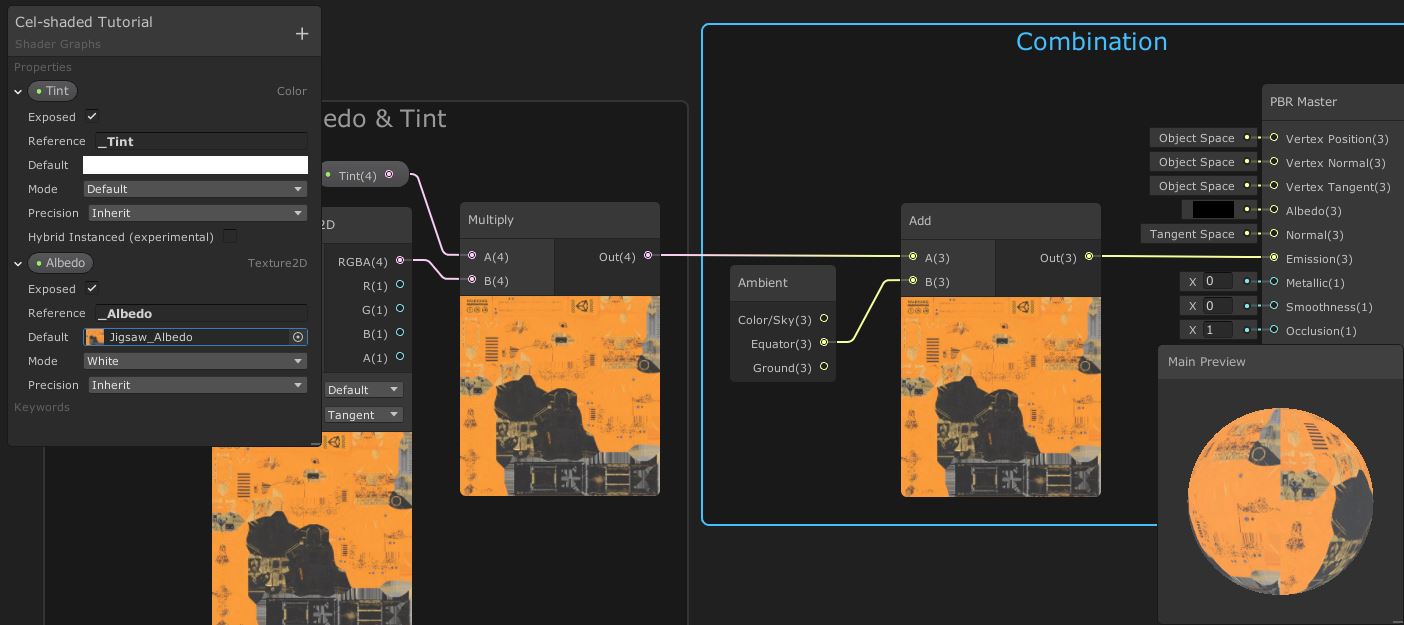 The
The Ambient node provides ambient light out of the box.
Now we’ll handle diffuse light, which is a bit more complicated. We established that we need the normal and light direction vectors - it’s easy to get the first using the Normal Vector node, but unfortunately there’s no node for getting information about the lights in the scene. We’ll have to use a Custom Function node instead.
Custom Function Nodes
In order to get lighting information in our graph, we’ll need some custom code. It’s a bit of a cumbersome workaround but bear with me! Unity still provides an extensive API for shader code, and we can use as much or as little of it as we want alongside the features of Shader Graph. To simplify things, we’re only going to include code to handle one directional light in the scene - if you need to consider multiple lights in the scene, you’ll want to check out Alex Lindman’s tutorial on this same topic after finishing this article; I’m using many of the concepts from this tutorial myself!
We’ll work backwards and write the code first. Then, we’ll create a Custom Function node that uses the code. We’ll wrap the node in a Sub Graph, and finally, we’ll use the Sub Graph in our main graph. If you’re not interested in what the code does, skip to the bottom of this subsection and copy the completed code chunk into this file.
Create a new file and name it GetLighting.hlsl - the extension is important, but you can change the name if you’d like. In this file, we’ll write a single function called MainLight_half. The _half is important because Shader Graph allows us to choose the precision of the functions we use, so we could write variants of this function in the same file - for example, with the suffix _float - so that Unity can use an alternative level of precision. But that won’t be important for us.
The function is going to take in a WorldPos as input and output the Direction, Color and Attenuation of the light - but we need to define all four in the function parameters and specify which are outputs using the out keyword.
void MainLight_half(float3 WorldPos, out half3 Direction, out half3 Color, out half Attenuation)
{
...
}
Inside the function, we’ll need to use directives to determine where this object is being rendered. If Unity is rendering a preview window inside Shader Graph, it doesn’t actually have access to a main light at all, so we’ll provide “fake” output values to pretend there is a light.
#if SHADERGRAPH_PREVIEW
	Direction = half3(0.5, 0.5, 0);
	Color = 1;
	Attenuation = 1;
#else
    ...
#endif
Next, we’ll need to check if the main directional light is casting shadows. We need another directive to do this, which we will nest inside the else-block of the first directive. We’ll then use Unity’s built-in functions to determine how we will retrieve lighting information. This is a bit out of scope for this tutorial so I’ll kind of gloss over this bit.
#if SHADOWS_SCREEN
	half4 clipPos = TransformWorldToHClip(WorldPos);
	half4 shadowCoord = ComputeScreenPos(clipPos);
#else
	half4 shadowCoord = TransformWorldToShadowCoord(WorldPos);
#endif
...
After this directive, we’ll retrieve the main light and extract the output data we need from it. Unity provides the GetMainLight function which returns a Light object, from which we can get the Direction and Color directly. For the Attenuation, we will need to multiply the distanceAttenuation and shadowAttenuation properties of the Light.
Light mainLight = GetMainLight(shadowCoord);
Direction = mainLight.direction;
Color = mainLight.color;
Attenuation = mainLight.distanceAttenuation * mainLight.shadowAttenuation;
And with that, we won’t need to do any more scripting for the rest of the article. Here’s the full code listing for those who skipped to the end:
void MainLight_half(float3 WorldPos, out half3 Direction, out half3 Color, out half Attenuation)
{
#if SHADERGRAPH_PREVIEW
	Direction = half3(0.5, 0.5, 0);
	Color = 1;
	Attenuation = 1;
#else
#if SHADOWS_SCREEN
	half4 clipPos = TransformWorldToHClip(WorldPos);
	half4 shadowCoord = ComputeScreenPos(clipPos);
#else
	half4 shadowCoord = TransformWorldToShadowCoord(WorldPos);
#endif
	Light mainLight = GetMainLight(shadowCoord);
	Direction = mainLight.direction;
	Color = mainLight.color;
	Attenuation = mainLight.distanceAttenuation * mainLight.shadowAttenuation;
#endif
}
Now we can add a Custom Function node to use this code. Click the cog menu in the top-right corner of the node to configure the inputs and outputs - we’ll need a Vector3 in the Inputs section, followed by two Vector3s and a Vector1 for the Outputs. You can rename each one by double-clicking the name once it’s been added. You will also need to change the Precision to Half using the drop-down at the top of the window. Next, select the File Type and select GetLighting.hlsl for the Source field. Finally, the Name is the name of the function without the precision extension - in our case, “MainLight”.

Custom Function requires you to specify the inputs and outputs.
Creating a Sub Graph
As a final step, we’ll wrap this in a Sub Graph for ease of use. Right-click the Custom Function node and select Convert to Sub-graph. You’ll be asked to create a new asset - I called mine MainLighting.shadersubgraph. Your code will break temporarily because the Sub Graph isn’t connected properly yet, so double-click the Sub Graph in the Project panel to open it. Like we just did for the Custom Function, we need to configure the Output node on this graph by clicking the cog menu and adding the same three outputs as the custom node, then connecting the pins. You should pass the Direction through a Normalize pin first so that our dot product calculations are correct.
We will also pass the world position into the custom node here. Create a Position node, select the World type from its drop-down and connect its output to the WorldPos input of the Custom Function node. Once you’re done, remember to click the Save Asset button in the top-left corner to make sure the main graph updates.
 We can use Sub Graphs to organise code effectively.
Back on the main graph, you should see a MainLighting node with the outputs we needed. We’ll be able to use that to implement Diffuse Lighting.
Implementing Diffuse Lighting
You should already have a MainLighting node (or whatever you called your Sub Graph) on the main graph, so next we’ll add a Normal Vector node with the Space set to World. We’ll perform the NdotL calculation by passing the Normal Vector and the Direction from the MainLighting through a Dot Product node. That was simple! We’ll Saturate the result - this will clamp the value between 0 and 1 - then Multiply its output with the Attenuation from MainLighting to account for shadows.
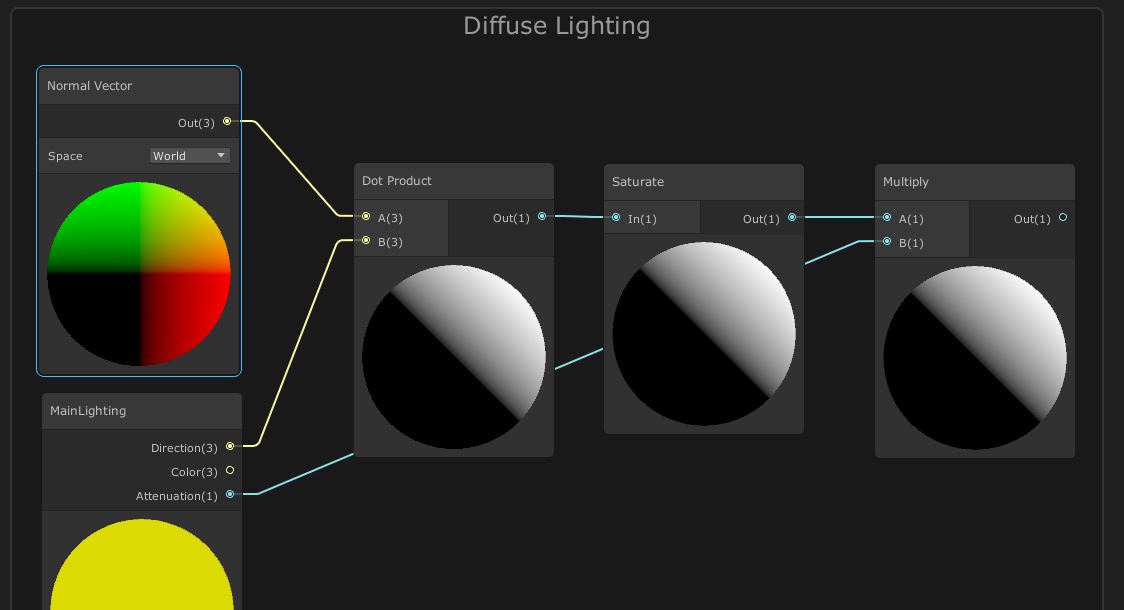 This is the basic NdotL calculation, plus attenuation.
Just before the existing ambient light Add node, Multiply the result of the Albedo & Tint group with the diffuse light we just calculated and pass its result into Add. Your main preview should now update to show a material with diffuse shading! If we pop into the Scene or Game View, an object with this material applied will now react to the directional light!
 By multiplying the original texture by the diffuse light, we’ll get shading on our material.
 The shading becomes darker where the sphere is not in direct light.
Implementing Specular Highlights
Now we’ll add the specular highlights. Remember that these are influenced by the view direction - what angle the camera is looking at the object - as well as the normal vector and light direction. We’ll start with the calculation of the half vector, then calculate NdotH.
Start off with a new MainLighting node (you can use the same one as before, but you’ll have wires hanging all over your graph) and wire its Direction pin to a new Add node. We’ll also create a View Direction node with its Space set to World, pass its output to a Normalize node (which sets the vector’s length to 1), then pass that into the other Add input. If we Normalize the output of Add, that will give us the half vector (strictly speaking, the half vector is the average, but we need to normalise the half vector before the next step anyway). Finally, create a new Normal Vector node and Dot it with the Normalize node - that’s NdotH done!
 The basic NdotH calculation.
Now we need to increase the strength of the specular light - if we added it now, we’d get a large white blob covering most of the material (including the bits that are meant to be darkened by the diffuse light) instead of a small, bright highlight. First, we’ll add a new property called Smoothness of type Vector1 to let us set the amount of specularity in the material Inspector - give it a default value of 0.5 and make sure Exposed is ticked. Then, Saturate the result of NdotH before piping it into the A field of a new Power node. Unsurprisingly, the Power node takes whatever is in A to the power of whatever’s in B. We’ll use the Smoothness node and Multiply it by 100 for the exponent, although we’ll also have to add a Maximum node so that it’s above zero.
After the Power node, we’ll do something a bit strange and create an Add node but leave the second argument as zero - we don’t need to use this yet, but later on we’re going to add the Fresnel lighting using this node. Create a Multiply node and drag a wire from the output of the Diffuse Lighting group into the first input - we don’t want specular highlights to appear on the back of the object - and connect the output of the placeholder Add to the second. Finally, Multiply by the Attenuation of the MainLighting node.
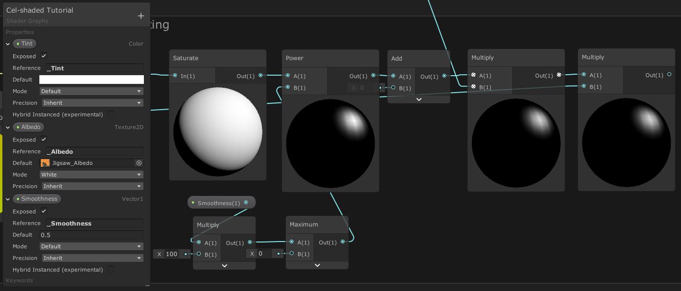 Adding a
 Smoothness property lets us modify the specularity from the Inspector.
To incorporate specular lighting into the material so far, we just need to Add together the result of the Diffuse/Albedo multiplication with the output of the Specular Lighting group. In the following screenshot, I’ve used a couple of sticky notes to make it a bit clearer which nodes are doing what - Shader Graph can get very cumbersome with nodes and wires hanging around everywhere! You can add your own sticky notes through right click->Create Sticky Note.
We ought to factor in the Color of the MainLighting node too - right before we add the ambient light, we’ll Multiply everything by the Color. The preview windows here are very useful for seeing what’s going on at each step - you should see a specular highlight appear from the Add node onwards.
 Adding Diffuse and Specular together.
If you check the material in the scene so far, you’ll get something like this:
 A specular highlight appears where the light shines on the object.
Implementing Fresnel Lighting
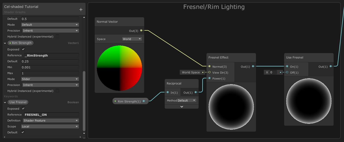
The final component of the basic lighting model is Fresnel lighting which, as discussed, looks like a thin amount of light bleeding over the grazing edge of an object - it appears where the viewing angle is shallow. We could calculate the Fresnel using the calculations we mentioned earlier, but Unity provides a Fresnel node out of the box, so drop one onto your graph. We’ll connect a new Normal Vector node (in world-space) to its Normal input and leave the default value for the View Dir input. For the Power input, we want to be able to control this in the material Inspector, so add a new property called Rim Strength of type Vector1 - this time, the Mode will be Slider and we’ll set the Min value to 0.001 and the Max to 1. I also set a Default of 0.25. The higher the input to Power, the thinner the Fresnel effect is - so we’ll take the Reciprocal of Rim Strength and use that for the Power. That’s why we set the minimum value to 0.001 - we don’t want to divide by zero.
If we leave things like this, we’ll run into a problem when we set the Fresnel to the minimum value - we might still see an extremely thin Fresnel on our object. To fix this, we need a way to turn off Fresnel completely. Here’s where Keywords are useful! Keywords give us a way to introduce branches into our shader in a safe way; if-statements in shaders often slow them down because the hardware can’t use prediction techniques, but with a keyword we can compile two versions of the shader - one which uses Rim Strength for the Fresnel, and the other that just returns zero.
We can add a keyword using the Blackboard plus-arrow menu. Select Keyword->Boolean, name our new keyword Use Fresnel and tick the Default field. We can drag the keyword onto the graph, which gives us a new node with On and Off inputs - the node takes the input depending on whether they keyword is set on or off. We’ll wire up the Fresnel calculations we’ve done so far into the On pin, and leave the default value of 0 for the Off pin. Remember the Add node we left as a placeholder while we were dealing with the specular lighting calculations? Connect the output of Use Fresnel to that node.
 We can use keywords to control which shader features are used.
Let’s see what this looks like on an object. If your Fresnel doesn’t appear on the material, then untick and re-tick the Use Fresnel field to make sure both variants of the shader get compiled properly. Also, if the tickbox doesn’t appear at all, Unity will only let you expose it to the material Inspector if the Reference has “_ON” at the end of its name (see this documentation).
 The edges of the sphere appear white on the side facing the light.
Lighting Ramp
Now that we’ve finished the lighting model, you’ll notice the material isn’t cel-shaded at all. We haven’t added any ‘hard cut’ to the lighting yet, which is central to the cel-shaded aesthetic. There are several ways to do that, but we’re going to use a lighting ramp texture - I’ve based this on what Ciro Continisio did in his tutorial. I’ve opted to use a different ramp texture for a slightly smoother shading effect; the hard cut is crucial for cel-shading, but there’s no reason it can’t have a subtly smooth transition rather than an immediate switch between light and dark. It’s down to personal preference which you pick.
The left side of the ramp texture controls how dark the lighting is at its darkest, and the right side controls how bright it is at its brightest - all values between control how the lighting transitions between dark to light. We’ll use separate ramps for diffuse light and specular+Fresnel light, but we can encode them both in one texture for efficiency. Here’s the lighting ramp texture I’ve used (it’s included in the project files at 128x2 resolution, and this version has an outline so you can see it properly):
 Two lighting ramps - one for diffuse and one for specular - included in one texture.
To start off, we’ll add two new properties for using the lighting ramp texture. The first will be a new Texture2D called Lighting Ramp - I’ve also set the default value to the lighting ramp texture so we can visualise the impact of these changes in the graph’s preview windows. Then, we’ll add a SamplerState (which I’ve named simply Sampler State) which lets us override how the lighting ramp texture is filtered. We need the Wrap mode to be set to Clamp so that lighting values above 1 don’t cause strange lighting effects.
We’re going to inject a few nodes right after the Diffuse Lighting and Specular Lighting groups. For both, we will use a Colorspace Conversion node to convert from RGB (red, green, blue) colour space to HSV (hue, saturation, value) colour space - this allows us to use the value (also called lightness) to control how far across the lighting ramp we sample. After the Colorspace Conversion node, we will use a Split node to grab only the B component of the colour (the outputs of Split unfortunately assume an RGB colour vector is used as input, but since we’ve input a HSV colour, it’ll output hue, saturation, value and alpha respectively for R, G, B and A).
Connect the Split node the X component of a Vector2 node and leave the Y value as 0. Now, use that Vector2 for the UV field of a new Sample Texture 2D LOD node, with the Lighting Ramp and Sampler State properties in the Texture and Sampler pins respectively. We’re using the LOD variant of this node so that Unity won’t ever use a mipmapped version of the lighting ramp - leave the default LOD value of 0. Finally, connect the output of this texture sample to the Multiply node that the Diffuse Lighting group was originally attached to.
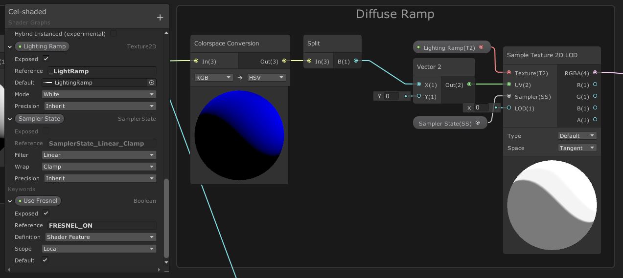 Converting to HSV lets us use the lightness channel to sample a lighting ramp texture.
Then, we’ll need to do all of the above between the output of the Specular Lighting group and the Add node that it’s connected to, with only one difference: the Y value of the Vector2 node is 1 instead of 0. The difference means that we sample the bottom row of pixels for the diffuse lighting, and the top row for specular and Fresnel lighting.
 The specular ramp sampling is identical, apart from the UV coordinates.
Normal Mapping
There’s only one more thing I want to add to this effect. For this, let’s apply the material to a more complicated model than a sphere - we’ll bring out the Ethan model that used to be included in Unity’s Standard Assets package. Ethan comes with a handful of textures we can use - so if we apply the material so far to him and see what he looks like…
 Ethan with diffuse, specular and Fresnel lighting.
…it’s pretty good so far! Obviously I’ve tinted him to better show off how lighting interacts on a more complicated model, but you should see the very fine details provided by the albedo texture (which is actually an occlusion map, but works fine here as an albedo texture). However, we’re missing a lot of detail. Ethan also comes with a normal map, which we can use to vastly improve the lighting. This part of the article is also based on what Ciro Continisio did in his tutorial. The following group of nodes will replace every instance of Normal Vector nodes on the main graph, so you can go ahead and delete all three times we used one.
We’ll start with one final Texture2D property called Normal Map. The Mode needs to be set to Bump but the rest of the values can be left to the defaults. Drag the property onto the graph and use it as the Texture pin of a Sample Texture 2D node - not the LOD variant, this time we want Unity to handle mipmapping automatically - and leave the UV and Sampler fields with the default values. We’ll also need to change the Type to Normal and the Space to Tangent. Also add a Normal Vector node (with its Space set to Tangent) and connect both that and the Sample Texture 2D into a Normal Blend node - this is going to blend the normal information from the mesh and the normal map.
Next, we need to transform the normals from tangent space into world space. There’s a node for that - Transform. It’s worth pointing out that Ciro did this step slightly differently because of a bug in an older version of Shader Graph, but whatever the bug is, it seems to be gone now. Stick a Transform node on the graph to transform between Tangent and World space, with Type set to Direction. Finally, Normalize the output. Now we can reconnect all instances where we need a normal vector in the graph with the output of this group.
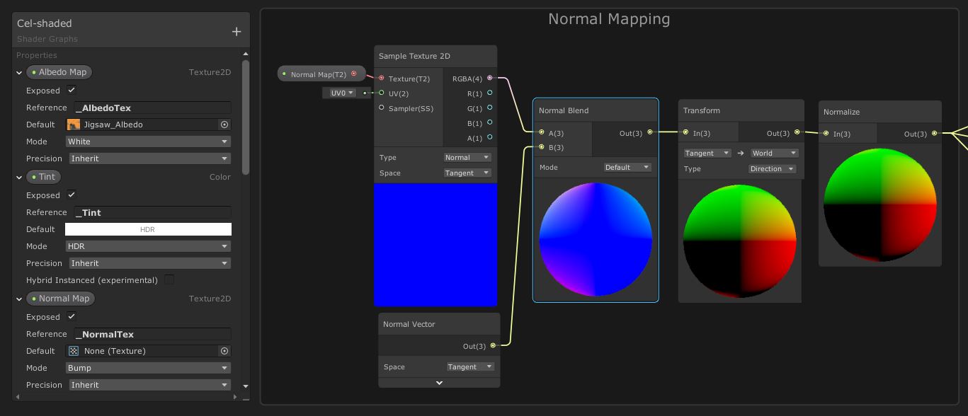 Setting up normal mapping.
With that, we’ve completed our cel-shading Shader Graph - congratulations for making it this far! Let’s have one final look at what this looks like in practice with the normal map applied to Ethan:
Conclusion
Shader Graph is a powerful and flexible tool for writing shaders. Unity provides such a huge variety of prebuilt nodes out of the box that you’ll be able to do so much without extra scripting, but it still gives you the option to add code if you need it. We’ve been able to create a configurable, efficient cel-shader using a combination of Shader Graph and scripting and used it to demonstrate the power of Universal Render Pipeline.