Outlines are an extremely popular method for making objects stand out in games. Plenty of developers choose to add outlines to advance an aesthetic like a comic book style. In this tutorial, we’ll take a SpriteRenderer and add outlines to it using Shader Graph. As always, the source code for this shader is available on GitHub.
Outline Shader
The approach we’ll take for this effect will be familiar to anyone who has used the Outline component bundled with Unity’s UI system. That script works by duplicating the UI element’s visual elements four times, tinting the duplicates a colour (usually black), then moving them up, down, left and right very slightly. Since the duplicates are drawn behind the UI element, it looks as if that element has an outline. We’re going to do something similar in Shader Graph for sprites. We’ll sample the texture normally for the base colour. Then, we’ll sample the pixels to the top, bottom, left and right of the current pixel and add together their alpha values. Assuming everything is fully opaque or fully transparent for a second, if the main texture sample has an alpha value of zero and the total alpha of the surrounding four pixels is above zero, then the current pixel is just one off the edge of the opaque section of the sprite and it should be drawn in the outline colour.
There’s a limitation of this approach you may have already seen - you won’t get outlines around corners. Sometimes that’s desirable, but other times you’d rather have those sections of outline. We’re going to add an option to do four additional outline texture samples to the top-left, top-right, bottom-left and bottom-right of each pixel.
Let’s get started by creating a brand-new Shader Graph by going to Create->Shader->2D Renderer->Sprite Lit Graph. You can also use a Sprite Unlit Graph - the only difference will be the light applied to the sprite, and everything in this tutorial will work the same. If you’re following this tutorial using the GitHub source, this graph will already be present, under Shaders/PixelOutline.shadergraph. If you’re doing this from scratch, make sure you have a SpriteRenderer in your scene to work with - the GitHub project already has a couple in the default scene.
The first thing we’ll do is sample the main texture. Since we’re attaching this to a SpriteRenderer, we’ll add a property called Main Texture and give it the Reference value _MainTex; Unity can automatically apply the SpriteRenderer’s sprite to this texture slot. Leave the Exposed tick box ticked. We need to use the alpha value of this texture to determine whether to draw the texture or to attempt drawing an outline, so once we’ve passed this texture into a Sample Texture 2D node, we’ll immediately pass its alpha output into a Comparison node, which performs Boolean operations. The operation drop-down will be set to Greater Or Equal, and the second input will be 0.5; this texture gets drawn only where its alpha is 0.5 or more. The output of the Comparison is passed into a Branch node’s Predicate input, and the full RGBA output of the texture sample gets passed into the True field of the Branch. The outline, which we’ll be calculating soon, is going to get passed into False. The Branch output gets passed into the Sprite Lit Master node’s Color input.
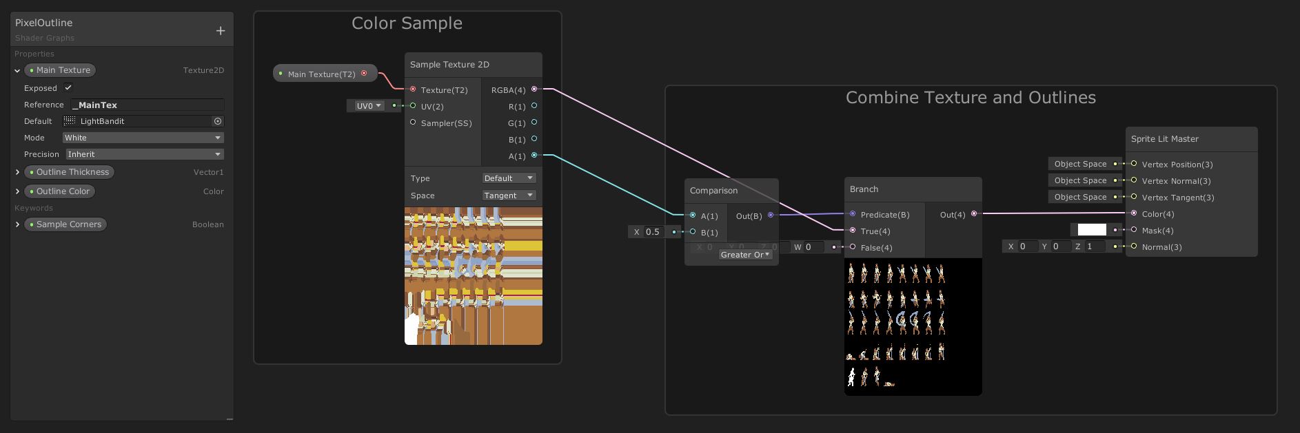 A Branch node can be used to change shader behaviour based on the sprite’s alpha.
Next, we’ll implement the ‘base case’, where we only want outlines to show up in the four cardinal directions. Since we’re going to be repeating the same process of sampling the texture and reading the alpha value four times (plus four more when we factor in the corners) with only slight differences in input, it’s a good idea to create a subgraph. That way, the main graph will be less cluttered than it would otherwise be. In the source project, you can find this subgraph under Shaders/OutlineSample.shadersubgraph, and if you’re creating a subgraph from scratch then go to Create->Shader->Sub Graph.
The subgraph will sample the main texture with an offset value which is based on the desired thickness of the outline and the ‘direction’ for this sample. For that, it will need a set of properties: Main Texture of type Texture2D; Outline Thickness of type Vector1; and Direction of type Vector2. Those will act as ‘inputs’ when we place a node of this subgraph on the main graph. Let’s work backwards. The subgraph will have two outputs - the RGBA colour value and the alpha value. The second one is just for ease so we don’t need to use a Split node to separate out the alpha channel. To add outputs, find the Output node and use the cog menu to add one output called RGBA of type Vector4 and another called A (for “Alpha”) of type Vector1. Feeding into that node is a Sample Texture 2D node with the Main Texture property as its texture input.
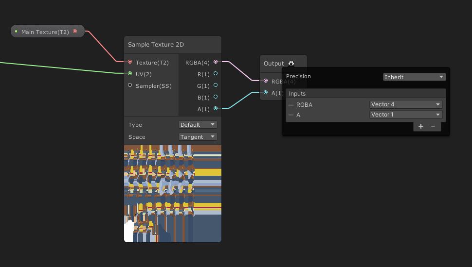 The extra alpha output eliminates the need to use a
 Split node later.
The UV parameter is a different story. We need to offset the main UV by an amount based on the other properties we pass into this subgraph, so feeding into the UV channel of Sample Texture 2D is an Add node, with a UV node passed into one of its inputs. The other input to Add is an offset value based on the size of the texture and the specified outline size. To get the size of Main Texture, we can pass it into a Texel Size node, which provides the width and height of the texture. We need to construct a new Vector2 based on those, then divide both values from 1 to get the fraction of UV space taken up by a single pixel. To do that, we can pass the Vector2 into a Reciprocal node. Then we need to multiply by Outline Thickness. Finally, multiply it by the Direction property to point the offset in the right direction.
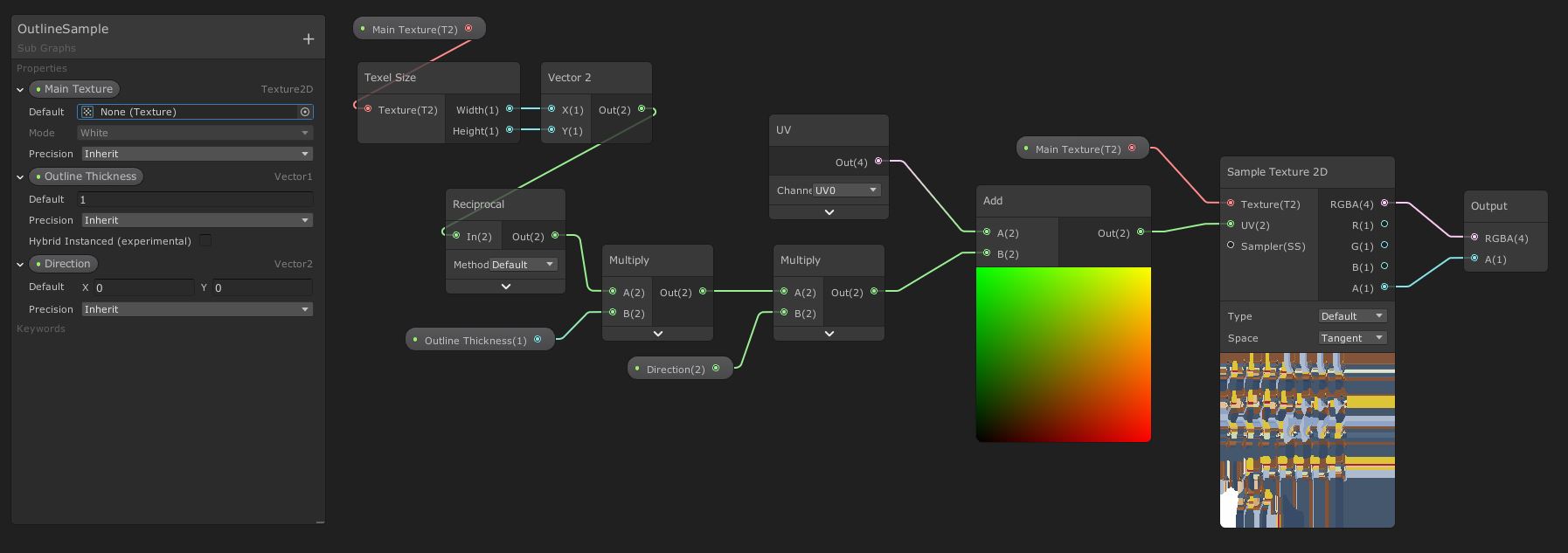 Now you can see why we used a subgraph - imagine this 8 times on a single graph!
Let’s go back to the main graph. First, add a new property called Outline Thickness of type Vector1 - this denotes how many pixels thick the outline will be. Also add a Color property called Outline Color - I hope it’s obvious what that does! Then, we can use the subgraph as a node on this graph by typing its name into the Create Node search box. We’ll need four of them - each one will have the Main Texture and Outline Thickness properties plugged into its inputs, but each has a different Direction input: (0, 1), (0, -1), (-1, 0) and (1, 0) correspond to up, down, left and right respectively. We’ll Add their alpha outputs together pairwise, then Add those pairs together again to get a final sum for all outlines. At this stage, the result is a white blob which is slightly larger than the source sprite - it’s essentially the source texture tinted white and outlines in white. Throw in a bonus Add node which we’ll use later to add the extra four corner samples.
To calculate the colour of these outlines, we’ll use a Saturate node to clamp the outline values between 0 and 1. Then, pass it into a new Vector4 node’s W input; we’re going to act as if this Vector4 is a Color, since there is no node for constructing new Colors, so XYZW corresponds to RGBA. Drag the Outline Color node onto the graph and use a Split node to separate out the R, G and B components and hook them up to X, Y and Z respectively. The Vector4 can then be used as the input of the Branch node from before in its False slot.
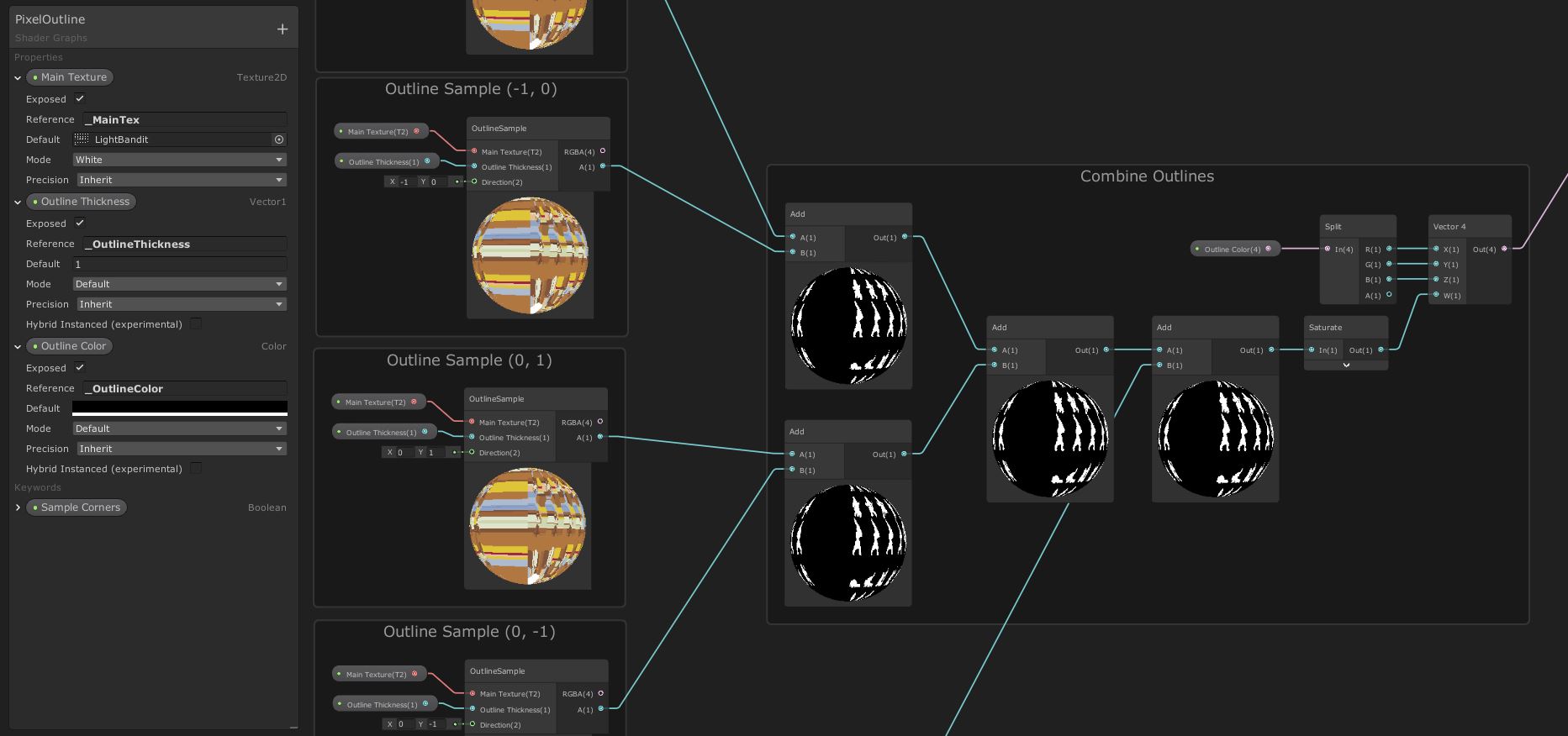 We can add all outline samples together to get a composite outline.
Let’s see what this looks like on the example sprites.
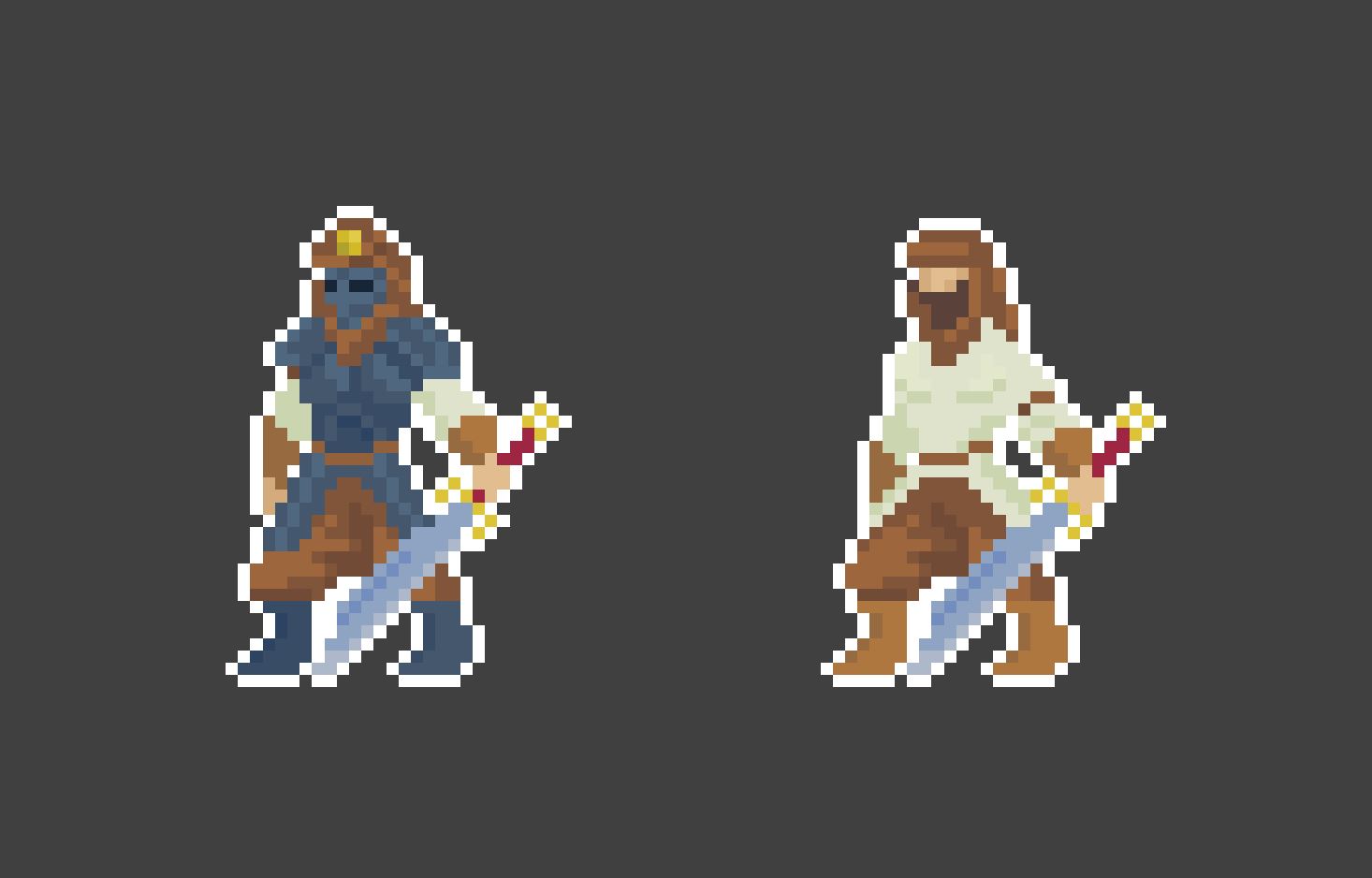 The outlines also update at runtime if a spritesheet animation is being used.
We could leave it here, but we also wanted to add an option to use ‘corner’ sampling in our graph. We can do that using a Boolean Keyword called Sample Corners with a Reference of CORNERS_ON (it’s important to include _ON so that it appears in the Inspector). We’ll leave it off by default and make sure the Definition is set to Shader Feature and its Scope is Local. Add four new OutlineSample nodes in the same configurations as before, with the following Direction values: (1, 1), (-1, -1), (1, -1) and (-1, 1). Add them together and feed them into the On slot of a new Sample Corners node; the Off slot’s value can stay at 0. The output of the node is then connected to the second slot of the bonus Add node from before.
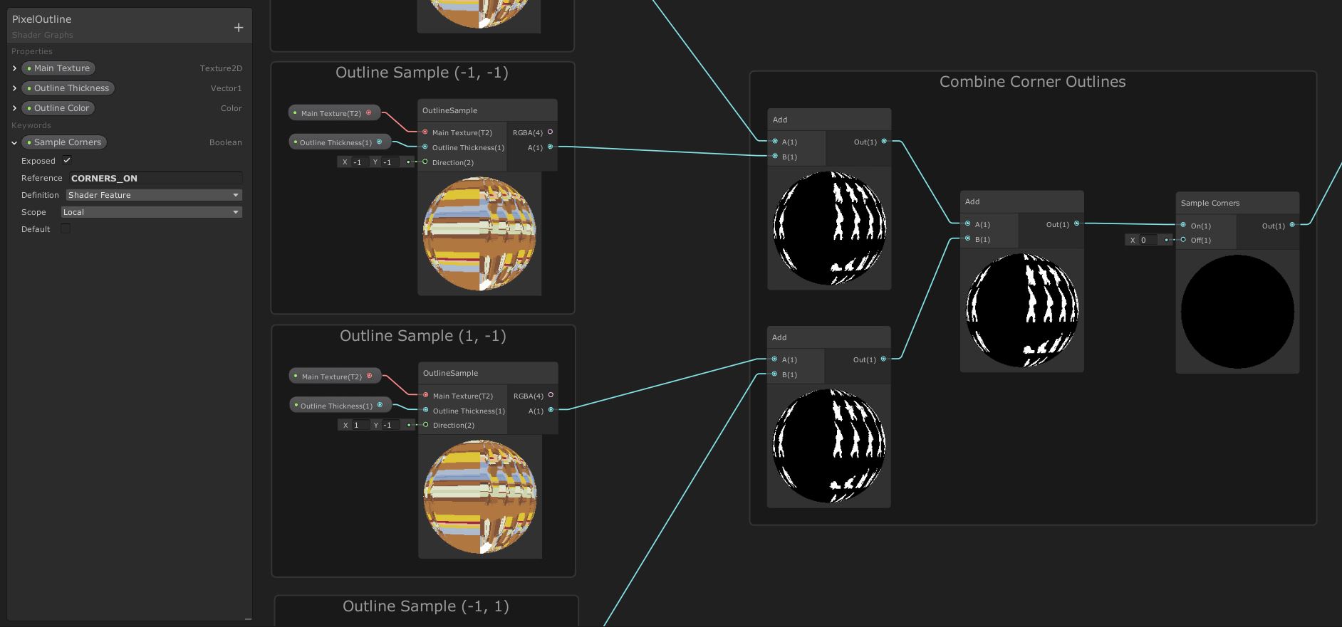 The same structure is used as before, with different Direction settings.
With the corner outlines enabled, let’s see the effect in motion:
Conclusion
Outlines are super easy to add in Shader Graph using its support for 2D graphs, even if they’re still labelled as “Experimental” in this version of Unity. This simple-to-understand technique takes multiple samples of the image at different UV coordinates and, depending on the alpha value of those samples, determines whether an outline or a regular texture should be drawn.
A poll was ran to decide which tutorial would be published this week - this article or one on rain and puddles in URP. Since the poll between Twitter and Patreon ended up as a tie, I’m also working on the rain tutorial. Look out for it in the coming days!
Acknowledgements
Assets
This tutorial uses the following asset pack:
| “Bandits - Pixel Art” | Sven Thole |