Decals will soon be supported natively in URP. However, I think it’s still useful to see how we can make our own in Shader Graph! Decals can be used to cover any surface - whether it’s curved or angled strangely - with a detail texture or sticker. Instead of plastering textured quads all over the scene positioned just in front of flat surfaces, we can place decal projectors over the surfaces to avoid z-fighting issues more easily.
This tutorial is aimed at people who have a bit of experience with Shader Graph. We are using Unity 2020.3.2f1 and URP/Shader Graph 10.4.0.
Check out this tutorial over on YouTube too!
Decal Theory
Decals are intended to be used when we want to project a texture on any surface, whether it’s flat or uneven. That makes it difficult to find a universal mesh-based approach, because we’d need to create new geometry to wrap round any mesh in order to render the decal. Instead, we’ll use some of the quirks of object space and the depth texture to map the decal texture onto a standard Unity cube. Sounds weird? Let me explain.
We’ll assume the texture is square for now. Conceptually, we will take a texture, place it at one end of a cube, then slide the texture down the cube volume until it hits an existing object, at which point, we’ll paint the object. How can we do that?
We can only render the surface of the cube, so unfortunately there’s no fancy trick where we force Unity to paint over the existing geometry which intersects the cube. But what if we decide to draw the cube after all opaque scene geometry has been drawn? Then we can draw the decal texture on the cube at the right position and make the rest of the cube transparent. We’ll use the depth texture to figure out which parts of the scene intersect the cube volume and only draw there. That requires us to reconstruct the world position from the depth texture.
 This is the intersection reconstructed from the depth texture. The whole outline is the decal cube.
Once we’ve done that, all pixels outside the intersection are deleted. But how will we decide which points are inside? Object space helps a lot here. Object space is where each vertex or edge of a mesh are defined relative to an arbitrary pivot point. For the standard Unity cube, the edges are 1 unit in length and the pivot is in the centre, so the vertices are at positions (0.5, 0.5, 0.5), (-0.5, 0.5, 0.5), and so on. Therefore, it’s easy to delete pixels outside the Unity cube by transforming from world positions - which we just recreated from the depth texture - to object positions, then checking whether the position is between -0.5 and 0.5 in all three axes.
 Pixels in the lower dotted square are ‘intersecting’. Others are not.
And what about texture mapping? That’s easy once we have the object position - just remove the z component, shift by 0.5 in both the x and y axes, and those are the UV coordinates. Then we can just map the texture and output to Base Color - let’s see all of this in action.
Decal Practice
Start with an Unlit graph by going to Create -> Shader -> Universal Render Pipeline -> Shader Graph. Also find your project’s Forward Renderer Pipeline Asset and tick the Depth Texture box - without this step, the shader won’t work. The Pipeline Asset is in Assets/Settings by default.
This graph only requires one property - the Main Texture. You can add others for Base Color and for Tiling/Offset if you wish, but I’ll stick with bare basics.
 Just one property this time.
This shader needs to be drawn after all other solid geometry, and we may wish to add support for transparent textures. In any case, we will need to go to the Graph Settings and change the Surface to Transparent.
 Those two tick boxes will be explained later.
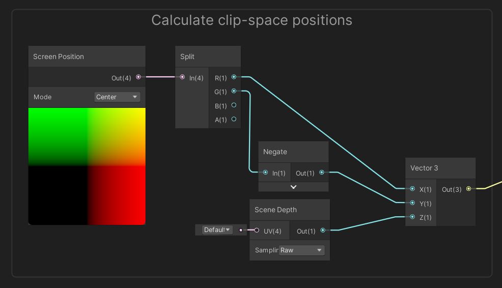
Let’s put some nodes on the graph. Unfortunately, the depth texture reconstruction process is a bit complicated, but I’ll step you through it. We’ll start with a Scene Depth node in Raw mode, which retrieves a value between 0 and 1 based on how far an already-rendered pixel is from the camera. The depth texture should contain all opaque objects in the scene at this point. These values represent the z-component of clip space, where all positions are relative to where they will appear on-screen, so I will add a Vector 3 with this Scene Depth in the Z component slot.
We also need to find the X and Y components. We can get these with a Screen Position node in Center mode, using a Split node to grab just the X and Y components. Use a Negate node to invert the Y component, because it’s upside-down.
 This gets us the positions in clip space.
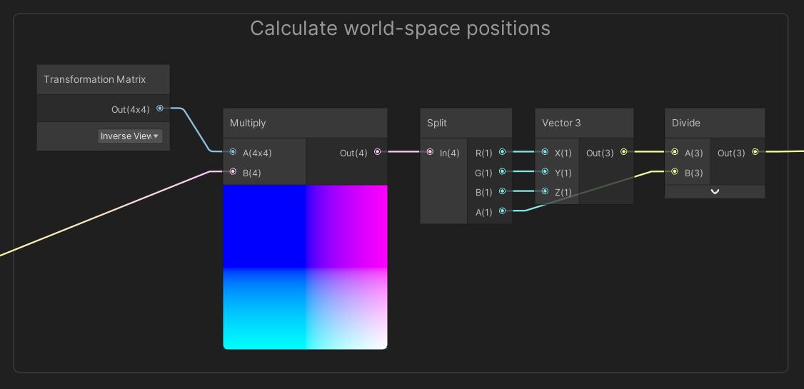
Unity uses a series of transformation matrices to take objects and turn them into screen pixels. The Model transformation goes from object space to world space, then the View transformation gets us to view space, and finally, the Projection matrix transforms everything to clip space, which is what we have right now. We want to unravel everything back to world space, so we need the Inverse View Projection matrix.
 Transformations: Not to be confused with Autobots or Decepticons.
Shader Graph provides all these matrices in the Transformation Matrix node, so select Inverse View Projection and multiply by the clip space Vector 3 - the order does matter, so make sure the matrix is in the A slot of the Multiply node.
The output is a Vector 4 rather than a Vector 3 - the reason why is a bit out of this tutorial’s scope, so look up homogeneous coordinates if you’re curious why. Basically, all we need to do at this point is divide the XYZ components by the W component to get the correct world-space XYZ position. Remember that RGBA on a Split node corresponds to XYZW.
 Space transformations can be a bit tricky to get your head around.
Now we have the world position. Awesome! But we need our positions to be in object space, so we’ll use a Transform node to convert between the two.
 Shame it wasn’t this simple to do every transformation.
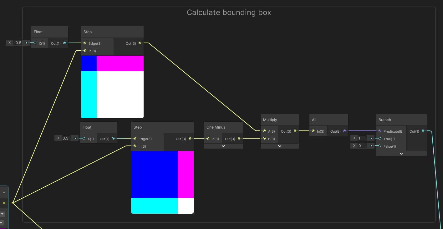
We’ll deal with clipping pixels on the cube that don’t intersect level geometry. We can do this by using a Step node, which will return 1 if the pixel visually intersects, and 0 otherwise - if we input a Vector 3, the comparisons are made per-component. Since the Unity standard cube spans from -0.5 to 0.5 in each axis, we will use two Step nodes: one provides the lower bound at (-0.5, -0.5, -0.5), and the other gives us the upper bound at (0.5, 0.5, 0.5). For the second Step node, we can use a neat trick where we use 0.5 as the threshold value then use a One Minus node to reverse the output values. Multiply the results together so that we have a value of 1 inside the cube and 0 outside. Then, pass it into an All node which returns true only if each input component equals 1. Finally, pass the result of the All node into a Branch node with 1 in the True slot and 0 in the False slot.
 We’re basically making a bounding box here.
Now let’s go back to the Transform node and think about the texturing process. As I mentioned before, the UVs are based on object-space positions, so all we need to do is add 0.5 in both axes to the object position to give us correctly-offset UVs - Unity will automatically ignore the Z component. Note that you may also need to set the texture wrapping mode on your main texture to Repeat in order for this to work. Then we can use a Sample Texture 2D node with the Main Texture and output the RGBA color to the Base Color on the output stack, then multiply the alpha with the zeroes and ones from the previous bounds-checking stage. This gives us a final Alpha value for the output stack.
 Texturing is easier to do than the bounding box.
You may also want to go back into the Graph Settings and enable Two Sided to make sure the decal gets projected in the right places, or use an Alpha Clip Threshold to cull pixels properly for a slight performance save.
That’s the decal finished! To add one to your scene, add a default Unity cube and add the Decal material to it. The texture will be projected along the z-axis of the cube, so make sure it is oriented correctly. Also, to avoid overdraw, make the cube as thin as possible while still covering the surface you want the decal to appear on.
 Completed decals look seamless in the Scene View!
Acknowledgements
Supporters
Support me on Patreon or buy me a coffee on Ko-fi for PDF versions of each article and to access certain articles early! Some tiers also get early access to my YouTube videos or even copies of my asset packs!
Special thanks to my Patreon backers for October 2021!
Gemma Louise Ilett
Jack Dixon Morrie Pisit Praiwattana Sébastien Perouffe
FonzoUA Josh Swanson Moishi Rand
Agnese Anna Voronova Brocktoon Christopher Pereira Hann Harshad James Poole JP Ming Lei Paul Froggatt Timothy Hanna Yasiel A. Ying Mo Zachary Alstadt