Many games need to show the player something on the other side of a wall. There are several solutions to this: a platformer might snap the camera just past the wall and zoom in on the target, whereas a stealth game might use “x-ray” vision to render enemies or other points of interest over the walls. There’s another approach we can use: just cut a big old hole in the wall using shaders. In this tutorial, we’re going to be using some shader techniques to do just that.
This tutorial is aimed at people who have at least some experience with Shader Graph. We are using Unity 2020.1 and URP/Shader Graph 10.2.2.
Check out this tutorial over on YouTube too!
Cutout Shader
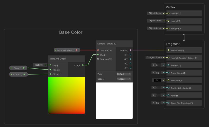
We’ll kick off by creating a new lit (PBR) shader - right-click in the Project window and select Create -> Shader -> Universal Render Pipeline -> Lit Shader Graph, then name your shader “WallCutout” or something similar. The first goal is to replicate the functionality of the standard lit shader, but we’ll cut corners like every game developer and just add a base texture for now.
Add three new properties: a Texture2D called Main Texture; a Vector2 called Tiling, with a default value of (1, 1); and another Vector2 called Offset, with a default value of (0, 0). We’ve dealt with basic texture sampling so many times now: drag the Main Texture onto the graph and plug it into the Texture slot of a Sample Texture 2D, then slot a Tiling And Offset node into the UV pin, with the Tiling property in the Tiling slot, and the Offset property in the Offset slot. Easy peasy! Slot the RGBA output into your output stack’s Base Color pin (which might be called Albedo on older versions), and we’re good to go. Feel free to add similar properties for Metallic, Smoothness, Emission and so on, but leave Alpha free.
 Bonus tip: Ctrl-left click properties and the Node Settings will show multiple properties at once.
 You can add extra properties and nodes for the other outputs, except Alpha and Alpha Clip Threshold.
Now we can work out where the cutout should be. We’re going to calculate the cutout location in screen-space via scripting and send it to the shader, so all we need to do now is add properties for it. Three more properties are needed: a Vector2 called Cutout Position; a Float called Cutout Size; and a second Float called Falloff Size. Because we need to pass data from a C# script, we’ll give these properties new reference values: _CutoutPos, _CutoffSize and _FalloffSize respectively.
 This is where I usually put some cutting remark, but you’ll probably tell me to cut it out.
We’re going to use opaque rendering, and then use an alpha cutoff for cutting the holes. We can head over to the Graph Settings window and enable Alpha Clip, which will activate the Alpha and Alpha Clip Threshold output pins. The approach we’re going to take is to compare the screen-space position of the pixel to the screen-space position of the cutoff, and if it’s within a threshold, we will cull the pixel. There’s a falloff, and we’ll use a dither pattern for that.
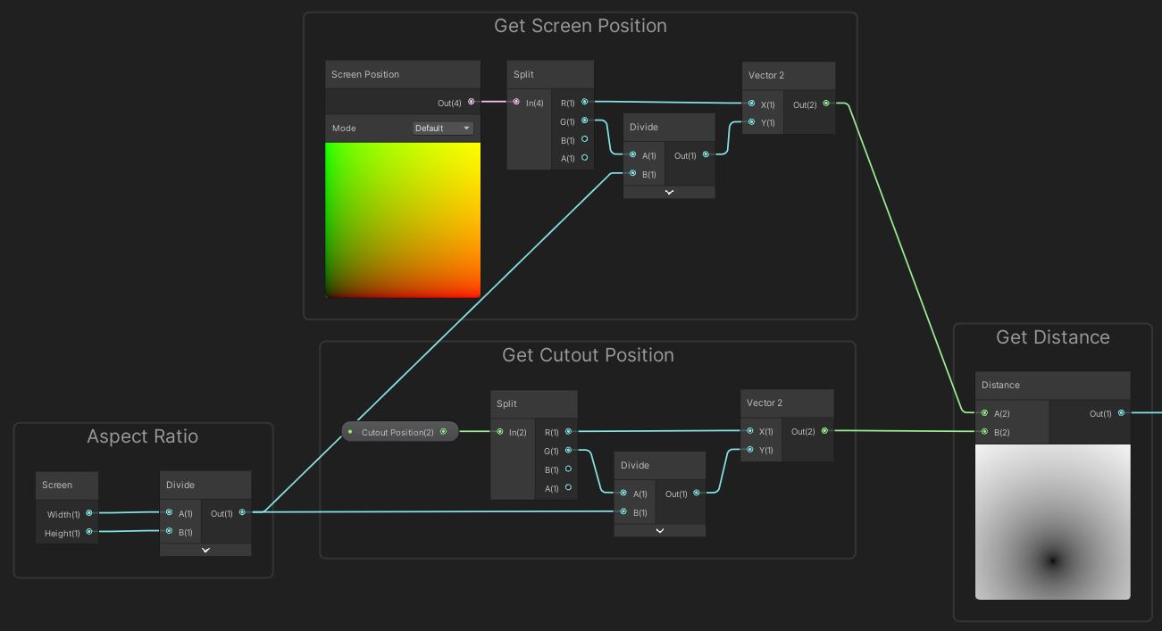
Those screen-space UVs go from 0 to 1 both horizontally and vertically across the screen, so to make the cutout circular, we need to take the aspect ratio of the screen into account. Start by adding a Screen node, then Divide the width by the height. That’s the aspect ratio! Now we can grab the screen position of the pixel being rendered. Use a Screen Position node for that, then use a Split node, because we need the X and Y components. Feed the X component right into the X component of a new Vector2 node, then multiply the Y component by the aspect ratio before feeding into the Vector2’s Y component.
We need to do the same process with the Cutout Position property. Once we’ve done that, we can plug both positions into a Distance node to get the Euclidean (straight-line) distance between the two. Using that distance, we can perform the cutout.
 One of the key aspects of this shader involves the distance between the pixel and the cutout centre.
We’re going to use Smoothstep so that we get a nice falloff between cutout and non-cutout areas. Smoothstep is a sigmoid function that returns 0 when In is below Edge1, 1 if In is above Edge2, and a smooth curve between 0 and 1 when In is between Edge1 and Edge2. We’ll use Cutoff Size for Edge2, the upper bound, and Cutoff Size minus Falloff Size for Edge1, the lower bound. The result from this node will be a cutout circle with smooth edges. We can multiply by 2 then pass this into a Dither node to get a lovely dithered circle, and output this directly to the Alpha on the master stack. The final step is to set Alpha Clip Threshold to something like 0.5, and we’ve got ourselves a fully-functional dither-based cutout which culls the right pixels. But what about passing data to the shader?
 Smoothstep gives us a soft alpha gradient, and Dither lets us keep opaque rendering.
Scripting
If we attach a material to the walls now, not much will happen. That’s because we need to send the location of the wall cutout to the shader via scripting. It shouldn’t be a huge script - we just need to convert the target object’s location to screen-space, raycast between the camera and the object to detect all the walls in the way, and send the location to all those walls. The shader handles the rest. I’ve created a new C# script called CutoutObject and attached it to the main camera - that’s important.
For the variables, we’ll need a reference to a targetObject Transform, which is the object we want to see through the wall. For the raycast, we only want to catch any walls between the camera and the target, so we will use a LayerMask called wallMask to ignore any collider not tagged with “Wall”. Finally, we will grab a reference to the Camera component in Awake using GetComponent.
[SerializeField]
private Transform targetObject;

[SerializeField]
private LayerMask wallMask;

private Camera mainCamera;

private void Awake()
{
     mainCamera = GetComponent<Camera>();
}
In Update, we can use the WorldToViewportPoint method on the camera to convert the targetObject’s position from world space to screen space - that’s convenient! We will need to divide the y-component by the screen’s aspect ratio, like we did inside the shader, so we’ll use Screen.width divided by Screen.height for the aspect ratio.
private void Update()
{
     Vector2 cutoutPos = mainCamera.WorldToViewportPoint(targetObject.position);
     cutoutPos.y /= (Screen.width / Screen.height);

     ...
}
We’ll be doing a Physics.RaycastAll, since we potentially want to catch multiple wall objects, because this returns an array of RaycastHit objects - each one contains useful information about one of those walls. We’ll start the raycast at the transform.position, and the direction will be the offset between that and the targetObject.position. For each hitObject we catch, we’ll grab the materials list - because the wall renderers might have several materials attached - and then for each of them, we’ll set the cutout position, cutout size and falloff size, thus sending the data to the shader we wrote. I originally planned to add code to scale the cutout position based on distance from the camera, but decided to leave that as an exercise for you. Consider it your maths homework for today.
Vector3 offset = targetObject.position - transform.position;
RaycastHit[] hitObjects = Physics.RaycastAll(transform.position, offset, offset.magnitude, wallMask);

for (int i = 0; i < hitObjects.Length; ++i)
{
     Material[] materials = hitObjects[i].transform.GetComponent<Renderer>().materials;

     for(int m = 0; m < materials.Length; ++m)
     {
          materials[m].SetVector("_CutoutPos", cutoutPos);
          materials[m].SetFloat("_CutoutSize", 0.2f);
          materials[m].SetFloat("_FalloffSize", 0.05f);
     }
}
Over in the Scene View, I’ve attached colliders to each wall in my example scene and given them a layer called Walls. The CutoutObject script on the main camera uses that layer for the wallMask, and once we attach a targetObject, we’ll see effects in Play Mode immediately!
 We can see the target through the wall!
Limitations
All effects come with possible improvements, and for this effect, the key pitfalls are the inability to scale the cutout with distance (you’ll need to code that yourself) and the problem encountered if two wall objects are next to each other, but the raycast only hits one of them.
The first problem could be fixed by scaling the size manually, or with a slightly tweaked approach, for example using the stencil buffer. I deliberately didn’t use that approach because I’ve already seen it done in an excellent tutorial by Daniel Santalla - you should totally check it out! It’s also a lot more difficult using the stencil buffer with Shader Graph and I couldn’t work out how to dither the edges with that approach.
The second could be fixed using an alternative type of raycast, such as a SphereCast, which projects a sphere along a ray. That gives your ray a ‘thickness’ which would definitely catch adjacent walls, if you make the sphere radius the same size as the cutout size.
Acknowledgements
Assets
This project uses the 3D Free Modular Kit (affiliate link) by Barking Dog. Woof. Their other assets look genuinely quite cool too!
Supporters
Support me on Patreon or buy me a coffee on Ko-fi for PDF versions of each article and to access certain articles early! Some tiers also get early access to my YouTube videos or even copies of my asset packs!
Special thanks to my Patreon backers for March 2021!
Gemma Louise Ilett
JP Pablo Ruiz
Jack Dixon Paul Froggatt Tuomas Männistö Sébastien Perouffe
Chris Sims FonzoUA Jesper Kuutti MR MD HARDING Maya Nedeljkovich Moishi Rand Shaun Wall
Anna Voronova Christopher Pereira Harshad James Poole sadizeng Zachary Alstadt
And a shout-out to my top Ko-fi supporters!
Dan Violet Sagmiller Be-Rad Hung Hoang Arthur H Megan Taylor Takuya “Somebody”