This tutorial explores the retro console shaders found in Snapshot Mode, which emulate the look and feel of the Nintendo Entertainment System (NES), Super NES (SNES), and Game Boy (GB). We will explore the colour transformations involved and implement an effect that makes the image appear as if it is being displayed on an old-style CRT screen.
NES
The NES colour palette is strange when compared to modern hardware. There are 64 colours in the palette, some of which are either duplicates or unusable, leaving 54 effective colours. On top of that, there are three colour emphasis ‘modes’, which arguably pushes the range to 432 colours across 8 modes, although we can only use 54 at a time. Worse for us, these colours are in the YIQ colour space - not RGB. If we wished to emulate the NES colours exactly, we would convert the screen image to YIQ, pick the closest colour in our small range of available colours, then convert back to RGB.
But there’s no point in worrying about all this - after all, most of computer graphics is made up of trickery and faking things. Instead, we’re going to stay in the RGB colour space. We’ll quantise each colour channel from a continuous range between 0.0 and 1.0 into four values - quantisation is the process of mapping some set of values to a smaller set of values - leaving us with 64 possible colours. There are a few more possible colours than the NES could handle, but it won’t be noticeable. It’ll feel “retro”.
Let’s look at the template shader file found in Shaders/PixelNES.shader. It’s very simple - like the old Greyscale and Sepia Tone templates, all this shader does is output the main texture without modification. All our work will be done in the fragment shader - we don’t need to add anything to Properties.
fixed4 tex = tex2D(_MainTex, i.uv);

int r = 1;
int g = 1;
int b = 1;

return float4(r, g, b, 1.0);
We’re going to exploit integers to quantise the image. Since we know we want four colours per channel, we’ll multiply the individual R, G and B values by four, truncate them to integers, then divide to get our values back into the [0, 1] range. I’ve subtracted a tiny amount - an ‘epsilon’ value - off the original RGB values during the calculation because otherwise a value of 1.0 would be quantised to 4, but we only want four possible values: 0, 1, 2 and 3. Remember that truncation will turn a floating-point value of 3.999 into an integer value of 3.
// With other variable definitions.
static const float EPSILON = 1e-10;

// Inside fragment shader.
int r = (tex.r - EPSILON) * 4;
int g = (tex.g - EPSILON) * 4;
int b = (tex.b - EPSILON) * 4;
We’ll then divide each channel by the maximum int value - 3 - to obtain the final RGB values, which are floating-points between 0 and 1.
return float4(r / 3.0, g / 3.0, b / 3.0, 1.0);
Run the shader effect by dragging an ImageEffectBase component onto your main camera and attaching the shader - it should result in an effective colour transformation. However, we’re missing the pixelated feeling of an old NES game.

Pixelation
We looked at downsampling an image back in the Blur tutorial. The effect we’re looking for is to make our image smaller, perform the colour transformation on the smaller image, then expand the image back to screen size - but if we did this the same way as before, it’d blur the result. As a starting point, we shall do the same as before and then discuss how to avoid the blurring. We’ll create a new C# script called ImageEffectPixelate.cs and let it inherit from ImageEffectBase.
using UnityEngine;

[RequireComponent(typeof(Camera))]
public class ImageEffectPixelate : ImageEffectBase
{
	[SerializeField]
	private int pixelSize = 2;

	protected override void OnRenderImage(RenderTexture src, RenderTexture dst)
	{
		int width  = src.width / pixelSize;
		int height = src.height / pixelSize;

		RenderTexture temp =
			RenderTexture.GetTemporary(width, height, 0, src.format);

		// Obtain a smaller version of the source input.
		Graphics.Blit(src, temp);

		Graphics.Blit(temp, dst, material);
	}
}
So far, the script downsamples, runs the shader on the smaller image, and upsamples it back to normal size. To avoid the interpolation of the temp texture when we call the final Blit(), we can modify the filter mode of the image - the default setting is FilterMode.Bilinear, which we shall change to FilterMode.Point right after creating temp.
// Make sure the upsampling does not interpolate.
temp.filterMode = FilterMode.Point;
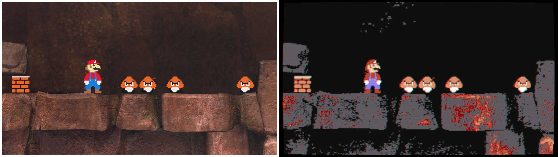
Now attach this script to the camera instead of ImageEffectBase and insert the PixelNES shader. You can change the amount of downsampling by modifying the pixelSize in the Inspector - my recommended value is 3. This is looking a lot more like the effect we want.
![]()

SNES
Now let’s look at the SNES filter. The colour palette was, of course, more advanced than that of the NES - there’s now support for 32,768 colours, with 256 at once. However, the hardware also supported additive and subtractive colour blending, so the “256 at once” becomes “any combination of two of those 256 colours at once”. It gets very complicated beyond that, so we’re going to give each of the three colour channels six possible colours, giving us only 216 colours on the screen at once - but it’s noticeably more than the NES effect, so we’ll go with that.
The shader takes the same form as the NES shader, but with different constants in the calculation. Open Shaders/PixelSNES.shader and modify the fragment shader.
fixed4 tex = tex2D(_MainTex, i.uv);

int r = (tex.r - EPSILON) * 6;
int g = (tex.g - EPSILON) * 6;
int b = (tex.b - EPSILON) * 6;

return float4(r / 5.0, g / 5.0, b / 5.0, 1.0);
Looking good so far! Together with ImageEffectPixelate, the effect is looking quite strong. However, I think we can go one step further with the effect - NES and SNES games were played on CRTs, which certainly don’t look this crisp. We’re going to implement features to make our effect more like the Snapshot Mode effect, then go above and beyond.

CRT
CRT stands for “cathode ray tube”; a CRT TV operates by firing electrons into a phosphorescent screen to generate light and, by extension, images. There are three colours of phosphor used - red, green and blue - which is very convenient for us. Images are produced by scanning left-to-right, top-to-bottom, row-by-row, until all pixels have been displayed, then the process starts over again. The gaps between the phosphor zones and the action of the CRT scanning along rows means that visible scanlines appear horizontally on the screen. What we’re going to do is split the screen into those phosphor zones with a dead zone where the scanlines would appear - in effect, the screen will be segmented into 3x3 sections, with three 1x2 vertical lines for each of red, green and blue, with a 3x1 black horizontal line below them. We’ll multiply the source image by this ‘grid’ to obtain the final image.
Open the Shaders/CRTScreen.shader template file. This time, we’re going to have to add something to the vertex shader - exciting, I know! We need to know the screen coordinates of each fragment later, so we’re going to calculate them in the vertex shader and then they’ll be interpolated later. We’ll use appdata_img included in UnityCG.cginc to pass data into the vertex shader, but we can’t use v2f_img or vert_img because we need to pass over the screen position.
struct v2f
{
	float2 uv : TEXCOORD0;
	float4 vertex : SV_POSITION;
	float4 screenPos : TEXCOORD1;
}

v2f vert (appdata_img v)
{
	v2f o;
	o.vertex = UnityObjectToClipPos(v.vertex);
	o.screenPos = ComputeScreenPos(o.vertex);
	o.uv = v.texcoord;
	return o;
}
In the vertex shader, after we’ve transformed the vertex in appdata_img to clip space, we’ll use the clipped vertex position in the ComputeScreenPos() function to determine the screen position. This will be passed to the fragment shader inside v2f’s screenPos variable. If you’ll recall from Part 5 of this series, one of the things I talked about was TEXCOORD semantics - for compatibility with some DirectX-based systems, we need to specify a semantic on each variable inside this struct. I could have chosen another semantic like COLOR0 to hold screenPos, but I’ve chosen TEXCOORD1 because it’s generally higher precision. It gets confusing since this data is neither a colour nor a texture coordinate, but just roll with it - you can pass arbitrary data with these named semantics.
Now let’s look at the fragment shader. As usual, we calculate the pixel colour using the normal uv coordinates. We’re going to need a way to determine if this is a ‘red pixel’, or a ‘blue pixel’ and so on, and we’re also going to determine whether this is a ‘scanline pixel’. We’ll modify our input pixel colours based on where on the screen the pixel is situated.
fixed2 sp = i.screenPos.xy * _ScreenParams.xy;
The first step after reading the input texture is to calculate the screen pixel coordinates - this is what we’ll be using later. The screenPos variable denotes where our pixel is on the screen, normalised in the x- and y-axes in the range [0, 1], and _ScreenParams is a built in variable whose x and y members contain the pixel width and pixel height of the camera’s target texture (which in this case, is the entire screen texture). The result of multiplying them is the pixel coordinate on the screen of this fragment.
Now we’ll exploit some nice features of matrices.
float3 r = float3(col.r, 0, 0);
float3 g = float3(0, col.g, 0);
float3 b = float3(0, 0, col.b);

float3x3 colorMap = float3x3(r, g, b);
We’ll separate each colour channel into their own vectors with the other colour channels zeroed out. Then, we can collate them together into a 3x3 matrix - this step will become clearer in a little while.
Then, we’ll deal with scanline rows versus normal rows.
float3 wh = 1.0;
float3 bl = 0.0;

float3x3 scanlineMap = float3x3(wh, wh, bl);
A row will either get multiplied by full white or full black. We’ll do the same thing as above by putting those row colours into a matrix.
Now comes the smart bit where we use those matrices. Did you know you can access the rows of a matrix by treating the matrix like an array? We’re going to pick a row out of colorMap based on which pixel column this pixel is in, and we’ll pick a row from scanlineMap based on the row the pixel is in. Since our ‘blocks’ are 3x3 pixels large, we’ll use the pixel x- and y-coordinates modulo three as our ‘array indices’. Then, we use component-wise multiplication on both the retrieved colour vectors. The result is that the colour of a pixel in a ‘red’ column and a ‘white’ row will become equal to the red component of the input colour. Similarly, any pixel on a ‘black’ row will have all its components multiplied by zero, so it will be black.
fixed3 returnVal = colorMap[(int)sp.x % 3] * scanlineMap[(int)sp.y % 3];

return fixed4(returnVal, 1.0);
Did all that make sense? Running the shader now, the effect works, but it’s very dark because of the scanlines! Also, we can do a little something to bleed the colour channels a little - CRT TVs were not as crisp as today’s LCD or OLED technology.
The latter step is easy - just modify the colorMap matrix rows to include a little bit of the other colour channels, like this:
float3 r = float3(col.r,     col.g / 4, col.b / 4);
float3 g = float3(col.r / 4, col.g,     col.b / 4);
float3 b = float3(col.r / 4, col.g / 4, col.b);

float3x3 colormap = float3x3(r, g, b);
Now we’ll modify the brightness and contrast of the image a little to improve the darkness shift introduced by the scanlines. For this, we can introduce a couple of parameters.
// In Parameters.
_Brightness("Brightness", Float) = 0
_Contrast("Contrast", Float) = 0

// In the shader pass, near _MainTex definition.
float _Brightness;
float _Contrast;
Now we’ll modify the output colour using these variables. Brightness is going to be a linear increase to all three colour channels, and we’ll use contrast to emphasize the difference between different colours and shades. Without contrast in addition to brightness, the resulting image looks a bit muddy and greyed out.
returnVal += (_Brightness / 255);
returnVal = saturate(returnVal);

returnVal = returnVal - _Contrast * (returnVal - 1.0) * returnVal * (returnVal - 0.5);

return fixed4(returnVal, 1.0);
If you run the shader effect now, nothing will be different because the brightness and contrast values haven’t been set. We’ll write another simple C# script to handle this for us. It should already be there in your template project, but if you’re writing from scratch then it’s a short script. Call it ImageEffectCRT.cs and put it in the Scripts folder.
using UnityEngine;

[RequireComponent(typeof(Camera))]
public class ImageEffectCRT : ImageEffectBase
{
	[SerializeField]
	private float brightness = 27.0f;

	[SerializeField]
	private float contrast = 2.1f;

	protected override void OnRenderImage(RenderTexture src, RenderTexture dst)
	{
		material.SetFloat("_Brightness", brightness);
		material.SetFloat("_Contrast", contrast);

		Graphics.Blit(src, dst, material);
	}
}
Instead of attaching the CRTScreen shader to an ImageEffectBase component, try attaching it to an ImageEffectCRT component instead. All being well, the CRT effect is complete! Play around with the values until you find something you like - the values in the script were my preferred values.

To emulate the look and feel of an NES or SNES game, I recommend attaching - in order - an NES/SNES filter, a CRT filter and then a Bloom filter to the camera. For this reason, I’ve included the Bloom shaders and script from the first half of this series in the template project for you to use. The bloom filter emulates the glare you might get from an old CRT.


Game Boy
The Game Boy (GB) had a comparatively much simpler colour palette than either the NES or SNES - four shades of green (or, on the Game Boy Pocket, four shades of grey). We’ll use a similar technique as in the Greyscale shader to map the original pixel colour values to GB colours.
Open the Shaders/PixelGB.shader template file. Our fragment shader calculates the luminance of the input pixel to use as our ‘base’ value. We’ll need to posterise the image as before, so we’ll exploit integers again.
float lum = dot(tex, float3(0.3, 0.59, 0.11));

int gb = lum * 3;
This gives each pixel one of four values for the gb variable: 0, 1, 2 or 3. Those will each map to an output colour. If we were using the GB Pocket colour palette, we’d just divide through by three and output that as the colour, but all we’d get is a quantised greyscale effect - that’s not too interesting. Instead, we’ll output the original GB green shades.
// In Properties.
_GBDarkest("GB (Darkest)", Color) = (0.06, 0.22, 0.06, 1.0)
_GBDark("GB (Dark)", Color) = (0.19, 0.38, 0.19, 1.0)
_GBLight("GB (Light)", Color) = (0.54, 0.67, 0.06, 1.0)
_GBLightest("GB (Lightest)", Color) = (0.61, 0.73, 0.06, 1.0)

// After _MainTex definition inside shader.
float4 _GBDarkest;
float4 _GBDark;
float4 _GBLight;
float4 _GBLightest;
This gives us four colours to use as reference. Those default values are close to those used in the Game Boy, but feel free to tweak them. Now that we have four colours, let’s use our calculated gb value to pick between them. We haven’t discussed this before, but in shaders it’s usually bad practice to use if-statements in the same way you would in a CPU-based programming language. Because GPU hardware is very good at running the same instructions thousands of times in parallel, it’s not very good at switching branches in a statement like that. Instead, we can use built-in functions such as lerp and saturate - which are optimised for GPUs - to pick our values. In fact, using lerp and saturate together is a common idiom for switching between several values based on some factor.
float3 col = lerp(_GBDarkest, _GBDark, saturate(gb));
col = lerp(col, _GBLight, saturate(gb - 1.0));
col = lerp(col, _GBLightest, saturate(gb - 2.0));

return float4(col, 1.0);
We have seen saturate before - it bounds the value passed into it between 0 and 1. We have also seen lerp before, which gives us a value between its first and second parameters based on its third parameter. Since our input is an integer, the first line here asks the question “is gb greater than 0” - if not, set col equal to _GBDarkest, and if so, set col to _GBDark (since the third parameter to lerp is bounded to 1 by saturate). We then do this again, but after subracting 1 from gb. Now we’re asking “is gb greater than 1” - if not, don’t change the value of col, and if so, set col to _GBLight. This process of cascading through lerp calls and subtracting from a saturate is something you may see often.

Conclusion
We’ve looked at a few more shaders that take each pixel one at a time, but they’re a lot more in-depth than the Greyscale shaders of old. Perhaps you now have more of an appreciation for the difference between CRT and LCD screens, too. In the next tutorial, we’ll use a new type of kernel function to imitate the Oil Painting effect.