In preparation for this series, this article will provide some foundational material to get you ready to write shaders. Most of these topics will be revisited as the series goes on, so don’t worry if it doesn’t all click just yet - many of the upcoming tutorials will provide a skeleton for you to work with as you go along.
Writing shaders
Shaders in Unity are a bit of a weird beast. Unity uses a proprietary language called ShaderLab, which is more like a middleman between the properties exposed by Unity and a shading language - the actual shader code. We’ll explore the basics of ShaderLab syntax so you’ll have enough to understand the upcoming tutorials - for a complete guide, see the Unity Manual Shader Reference. If this all gets a bit much, then no worries: this gets easier as you go!
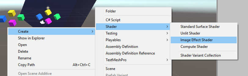
First of all, we’ll create a shader file in Unity (with file extension .shader) by right-clicking in the Project view and selecting Create -> Shader -> Image Effect Shader. Name it whatever you’d like, and a template is generated for you. Depending on the version of Unity you’re using, the generated code might differ, so from now on I’ll refer to ShaderLab code generally, without basing it on this template. ShaderLab code begins with the name of your shader, like this:
Shader "SMO/ExampleShader"
{
    // Shader code
}
In this example, the shader is named “ExampleShader” and can be found in Unity’s dropdown shader menu inside a folder called “SMO”. The first thing inside these braces is typically a Properties block:
Shader "SMO/ExampleShader"
{
    Properties
    {
        _MainTex ("Base (RGB)", 2D) = "white" {}
        _Albedo  ("Albedo colour", Color) = (1, 1, 1, 1)
        _Amount  ("Amount of something", Float) = 0.75
    }
    ...
}
Imagine Properties as being data your shader requires to function as expected. In this hypothetical shader, three properties are declared: a 2D texture/image, an albedo colour, and some floating-point number. The syntax for properties can get a bit finicky but bear with it - you won’t need to interact with this section too frequently, as the ‘meat’ of the shader comes later. Just know that there are a handful of types of data you can pass directly between Unity and your shader.
Next up, we will introduce the Subshader.
...
Subshader
{
    Pass
    {
        Name "MyPassName"

        CGPROGRAM
            ...
        ENDCG
    }
}
A ShaderLab file consists of a list of Subshader sections; Unity will pick the first subshader in the list that is supported by the hardware. For the sake of simplicity, the shaders we write will only have one Subshader.
A Subshader contains one or more Passes. A Pass will render something to the screen once - that could be a model with a shader attached, or in the case of an image effect, the screen itself is redrawn. When there’s more than one pass inside a subshader, they are executed in turn - the same object can be rendered to the screen multiple times by different shader passes.
Now we’ll cover some of the special features of Pass. We can Name our pass, as you see here. You usually don’t need to bother, although it’s possible to use a pass from a different shader file by referencing it by name. The meaty bit is the stuff after that - some bona-fide shader code, enclosed in CGPROGRAM ... ENDCG blocks. As I mentioned, ShaderLab is a kind of wrapper around a shader language; it’s not quite as clear-cut as this, but for now it will suffice to say our shading language is Nvidia Cg, which is itself a subset of HLSL (High Level Shading Language).
...
CGPROGRAM
    #pragma vertex vert
    #pragma fragment frag

    #include "UnityCG.cginc"

    struct appdata
    {
        float4 vertex : POSITION;
        float2 uv : TEXCOORD0;
    };

    struct v2f
    {
        float4 vertex : SV_POSITION;
        float2 uv : TEXCOORD0;
    };

    sampler2D _MainTex;
    float4    _MainTex_ST;

    v2f vert(appdata v)
    {
        v2f o;
        o.vertex = UnityObjectToClipPos(v.vertex);
        o.uv = TRANSFORM_TEX(v.uv, _MainTex);
        return o;
    }

    fixed4 frag(v2f i): SV_TARGET
    {
        fixed4 col = tex2D(_MainTex, i.uv);
        return col;
    }
ENDCG
...
Shader code, finally! But there’s a lot to look at here, so let’s go through this step by step.
#pragma vertex vert
#pragma fragment frag

#include "UnityCG.cginc"
We start off defining which functions are our shaders. We’ll be writing old-school vertex and fragment shaders - Unity also provides functionality for its own kinds of shaders like surface shaders, but we won’t be needing those. Our vertex shader is going to be called vert, and our fragment shader will be called frag. Those are just conventions - you can name them whatever you’d like. If you’ve never come across this terminology before, don’t worry - they are explained a bit further ahead.
The included UnityCG.cginc file contains a few helper functions, some of which we use later in the code; this file is a freebie and can be included in any Unity shader in this manner.
struct appdata
{
    float4 vertex : POSITION;
    float2 uv : TEXCOORD0;
};

struct v2f
{
    float4 vertex : SV_POSITION;
    float2 uv : TEXCOORD0;
};
We use structs to pass data between shaders. These names are also just convention, but the appdata struct is used to pass data from Unity to the vertex shader, and the v2f struct is used to pass the output of the vertex shader as the input to the fragment shader.
The appdata struct contains two variables - a four-element vector called vertex, denoting vertex positions, and a two-element vector called uv, denoting texture coordinates. As it turns out, the v2f struct also contains a vertex vector and a uv vector, although these ones will have been processed by the vertex shader so may be different to those from the appdata struct. POSITION and SV_POSITION are semantics that tell the hardware that these variables denote vertex positions, and the TEXCOORD0 similarly denotes that this is a texture coordinate; don’t worry about these special semantics too much, as we won’t really be doing anything interesting with structs in this series.
sampler2D _MainTex;
float4    _MainTex_ST;
_MainTex and _MainTex_ST are both variables. Remember way back inside the Properties section where we defined _MainTex as an input? Well, we need to tell our shader that we’re using it here. We’d need to do the same for any other properties, too, like colours or numbers. The type used for textures is sampler2D, presumably named as such because we take data from an image by “sampling” it. The _ST version of the variable contains scaling and UV offset data for the texture - all textures passed in Properties will have this additional variable.
v2f vert(appdata v)
{
    v2f o;
    o.vertex = UnityObjectToClipPos(v.vertex);
    o.uv = TRANSFORM_TEX(v.uv, _MainTex);
    return o;
}
It’s our vertex shader! A vertex shader operates on all the vertices of a mesh; in the case of an image effect, the four vertices are effectively the corners of the screen.
The syntax of shading language is deliberately similar to C. Our function, called vert, returns a v2f, and takes an appdata called v as input. The very first step is to define the output v2f and name it o, then the members of o are calculated. Here we see two facilities provided by UnityCG.cginc - the UnityObjectToClipPos function transforms the input vertices, defined in Unity world space, to the screen clip space, and the TRANSFORM_TEX macro takes the UV offset and scaling values we discussed above and uses them to modify the uv coordinates for the image.
In between the vertex and fragment shaders is a step called “rasterisation” - I won’t go into detail, but this converts the space between all the vertices into “fragments”. That leads us nicely to the fragment shader.
fixed4 frag(v2f i): SV_TARGET
{
    fixed4 col = tex2D(_MainTex, i.uv);
    return col;
}
A fragment shader is often called a pixel shader, because it essentially runs once for each pixel of the object. There are special cases where it runs on sub-pixel elements, but for the sake of simplicity, assume it’s just pixels.
It takes in the v2f that was output by the vertex shader, and calls it i, for “input”. The output of the shader is of type fixed4 - this is a four-element vector of floating-point values, which in this case denotes an RGBA colour (red, green, blue, alpha), where the alpha channel is transparency. In HLSL, float, fixed and half are each types of floating-point decimal numbers with decreasing precision, but they are often used interchangeably in cases where precision isn’t important, so you may also see a fragment shader that returns a float4 rather than a fixed4.
The tex2D function just samples the _MainTex image at the uv position output by the vertex shader, returning the colour of the pixel at that position.
To run this shader as a post-processing image effect, there’s a little more work to be done. Here’s a snippet of C# code that will apply our image effect.
using UnityEngine;

[RequireComponent(typeof(Camera))]
public class MyImageEffect : MonoBehaviour
{
    [SerializeField]
    private Shader shader;
    private Material material;

    private void Awake()
    {
        // Create a new material with the supplied shader.
        material = new Material(shader);
    }

    // OnRenderImage() is called when the camera has finished rendering.
    private void OnRenderImage(RenderTexture src, RenderTexture dst)
    {
        Graphics.Blit(src, dst, material);
    }
}
OnRenderImage() is an event function available to all classes that extend MonoBehaviour. If attached to a GameObject with a Camera component attached - a condition enforced by the RequireComponent attribute - then it will provide two RenderTexture objects I’ve called src and dst, representing the image as rendered by the camera and the image that will be output to the screen, respectively. We create a material using a shader, then use Graphics.Blit() to apply the shader to src and output the result into dst.
Just drag the shader we wrote into the shader slot in the Inspector in Unity, and you’re all set. You’ll notice that the shader doesn’t actually do anything yet but play around with the values inside the fragment shader. For fun, try messing with this sample fragment shader:
fixed4 frag(v2f i): SV_TARGET
{
    fixed4 col = tex2D(_MainTex, i.uv);

    // Modify any of the four values inside the fixed4() constructor.
    fixed4 returnCol = fixed4(col.r, col.g, col.b, col.a);

    return returnCol;
}
Conclusion
You should now have the prerequisite knowledge to tackle the upcoming shader projects for this series. Next time, we’ll be writing some basic image effect shaders to modify the colour of the image to greyscale and sepia-tone.