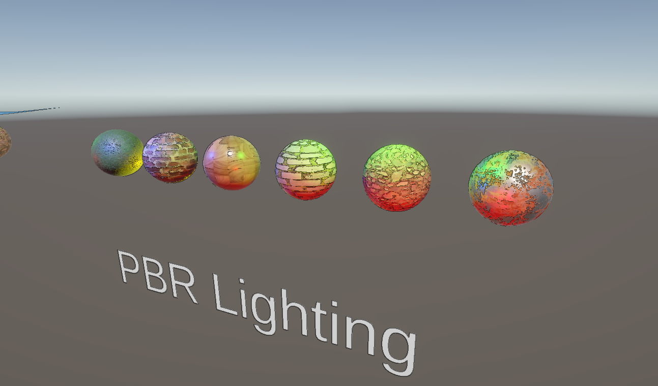
We’ve made lots of shaders which run on objects in the scene, but that’s not all that shaders are capable of. Post process effects run over the entire screen after everything has been drawn normally, and they let us manipulate the color of each pixel directly. URP comes with a few of these effects, like Bloom (which lets bright colors bleed into adjacent pixels) and Vignette (which overlays a darkened shadow oval around the corners and edges of the screen), but today we’ll make three effects of our own.
Best of all, we can hook our effects up to the same volume system that URP uses for its built-in effects. This method is a bit C# heavy, but we’ll go through it all step by step.
Render Graph
Let’s first talk about how Unity renders each frame. For this, let me introduce the Render Graph Viewer. To open it, you’ll need to go to Window -> Analysis -> Render Graph Viewer in the toolbar. If you don’t see a matrix of colored squares, then make sure the Scene View is currently visible in one of Unity’s windows, and that the selected camera in the drop-down at the top of the Render Graph Viewer tab is SceneCamera.
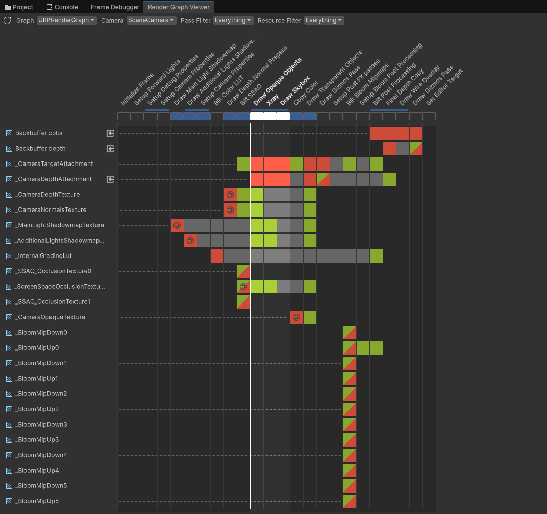
Along the top of the matrix of squares, you’ll see angled text listing the name of each step in the frame drawing process. Each one is a pass. These are high-level descriptions of the pass, like “Draw Main Light Shadowmap” or “Draw Opaque Objects”. Along the left, you’ll see the names of texture resources which Unity manages throughout the frame. Backbuffer Color and Backbuffer Depth can be thought of as the final screen color and depth textures, whereas _CameraTargetAttachment and _CameraDepthAttachment contain the contents of the screen at specific intermediate steps in the rendering process.
In the middle, a green square means that a specific texture is read from during a given render pass, whereas red means that pass writes to that texture. Read-write is represented by a split red-green color filling the square, and global textures are represented by a little globe symbol.
A good example is the _CameraDepthTexture. We used this texture in a previous tutorial to draw silhouettes, and we can now see that it is declared global and written to during the Draw Depth Normal Prepass, and then later, the Draw Transparent Objects pass (which includes the silhouette shader, which was in the transparent shader render queue) reads from that texture.
I’m giving you all of this information now because Render Graph is the system that Unity uses for drawing render passes in Unity 6 and up, and we’ll need to use it to write our own post process effects. It’s not the same kind of thing as Shader Graph, which is a node-based editing tool for shaders in which you directly create a visual graph. It’s a graph in the mathematical sense. Unity forms connections between each pass and figures out what dependencies exist between passes (e.g. if one pass reads from a texture which was written to by the previous pass, then there is a dependency on that previous pass), then optimizes the rendering loop by combining passes where dependencies don’t exist.
On this graph, we can click the Draw Opaque Objects pass (as in the above screenshot) and see that Unity draws an outline between it and the next two passes to signify that they have been merged. There are rules governing which passes can or cannot be merged (including the texture restrictions I mentioned, and the inability to use an UnsafePass which allows read-write operations in the same pass), but exploring these is a bit beyond this tutorial.
We can see that the Blit Post Processing pass happens near the end. In fact, it writes directly to the Backbuffer Color. The ‘post processing’ in this pass refers specifically to running URP’s included post process effect stack, so we are going to write our own render pass which happens just before or just after this one.
Subscribe to my Patreon for perks including early access, your name in the credits of my videos, and bonus access to several premium shader packs!

Greyscale Post Process
Let’s start off by creating an effect which turns the screen greyscale.
First, we need to create two scripts to drive the effect. If you go to Create -> Rendering -> URP Post Processing Effect, then Unity will create these two scripts for you, but I’m going to create both scripts from scratch so instead I’ll choose Create -> MonoBehaviour script instead. The first script should be called GreyscaleSettings, and the second can be called GreyscaleFeature.
Let’s start with GreyscaleSettings.
Greyscale Settings
This script contains all the settings that we can change for the effect. For URP’s included post process effects, when they are attached to a volume, each one can be toggled on and off, and they usually have a bunch of options to control how the effect appears. Our settings are simple: we’ll just have a single slider controlling the blend between normal screen colors and greyscale colors.
This class needs to inherit from the VolumeComponent class from the UnityEngine.Rendering namespace, which lets us attach it to a volume profile in the Unity Editor, and it should implement the IPostProcessComponent interface, which allows us to check if the effect is active later when we run the render pass. This class should also use the System.Serializable attribute so that its data can be saved properly, and we can use an optional extra attribute called VolumeComponentMenu to organize the menu where we add volume components to a volume profile. Just provide a name separated by forward slashes, and this name will be used when you try to add the Greyscale effect to a volume profile.
using UnityEngine;
using UnityEngine.Rendering;

[System.Serializable, VolumeComponentMenu("Basics/Greyscale")]
public class GreyscaleSettings : VolumeComponent, IPostProcessComponent
{

}
Next, we list out each of the parameters that we want to be able to tweak for this effect as member variables of this class. For this, we use some special types which all end in the word “parameter” – for instance, if we want a floating-point number parameter, you should use FloatParameter, and if it’s a color, then use ColorParameter. The strength parameter that we need for this effect is a float, but I also want to enforce an upper and lower bound for its values and display it as a slider in the Inspector, so we can use ClampedFloatParameter. Its constructor takes three values: the default, which I’ll set at zero, and then the lower and upper bounds which should be 0 and 1 respectively. There’s a whole host of different Parameter types, and we can create custom ones too, but let’s not get ahead of ourselves just yet.
public ClampedFloatParameter strength = new(0.0f, 0.0f, 1.0f);
Finally, we need to include a Boolean method called IsActive which returns true if the effect should run, and false otherwise. This method comes from the IPostProcessComponent interface. It should return true if the strength is higher than zero, and since it’s a special ClampedFloatParameter instead of a regular float, we say strength.value to get its raw value. We also want to check whether the little tickbox at the top of the volume component is enabled, so we can use an inherited member variable called active to check that.
public bool IsActive()
{
    return strength.value > 0.0f && active;
}
And that’s the settings script completed! Next, let’s turn our attention to the GreyscaleFeature script.
Greyscale Renderer Feature
This one is more complicated. First, it inherits from ScriptableRendererFeature from the UnityEngine.Rendering.Universal namespace. Scriptable Renderer Features are the mechanism that URP gives us for injecting custom behavior into the URP rendering loop.
The first thing I’ll add to it is a nested class called GreyscaleRenderPass, which itself inherits from ScriptableRenderPass. This is the basic structure of a custom post process effect in URP: a renderer feature, which manages the way that passes get injected into the URP rendering loop, and at least one render pass, which actually sets up resources and runs shader code.
using UnityEngine;
using UnityEngine.Rendering;
using UnityEngine.Rendering.RenderGraphModule;
using UnityEngine.Rendering.Universal;

public class GreyscaleFeature : ScriptableRendererFeature
{
    class GreyscaleRenderPass : ScriptableRenderPass
    {

    }
}
In the outer GreyscaleFeature class, let’s instantiate a GreyscaleRenderPass, and then we can override the Create method, which gets called whenever you first create the feature or change anything about it in the Unity Editor. It’s a good place to run basic setup code if we need to. Our example is fairly simple, so all I will do here is change the display name of the feature to “Greyscale”, although this is just a little cosmetic change when we add the feature to the renderer features list. I mostly just wanted to let you know that this method exists.
private GreyscaleRenderPass pass = new();

public override void Create()
{
    name = "Greyscale";
}

...

class GreyscaleRenderPass : ScriptableRenderPass
{

}
Next, more importantly, we have the AddRenderPasses override method. This one accepts a ScriptableRenderer and a RenderingData as parameters. For all intents and purposes, you can think of the ScriptableRenderer as being URP itself, and RenderingData is what it sounds like: information about the settings used by URP for rendering this frame. We won’t need the RenderingData here, but the renderer is very important.
First, let’s get the GreyscaleSettings. So, I told you that we’re using the URP volume system, and that means we need to detect whether a global volume is active or the camera is inside a local volume, and get the GreyscaleSettings from the corresponding volume if so, taking into account any blending between volumes. We can just say VolumeManager.instance.stack, which gives us the correctly-blended volume parameters, and call GetComponent to get the GreyscaleSettings specifically. If this is not null, meaning the camera is inside any volume containing a GreyscaleSettings, and that settings object is active – remember, we wrote the IsActive method to check whether the tickbox is checked and the strength parameter is above zero – then we will call upon the renderer to enqueue the pass.
private GreyscaleRenderPass pass = new();

public override void Create()
{
    name = "Greyscale";
}

public override void AddRenderPasses(ScriptableRenderer renderer, ref RenderingData renderingData)
{
    var settings = VolumeManager.instance.stack.GetComponent<GreyscaleSettings>();

    if (settings != null && settings.IsActive())
    {
        renderer.EnqueuePass(pass);
    }
}

class GreyscaleRenderPass : ScriptableRenderPass
{

}
That’s everything inside GreyscaleFeature done, so let’s move on to the GreyscaleRenderPass, which does most of the heavy lifting.
Greyscale Render Pass
First, let’s add a member variable to keep track of the material we use for applying the greyscale shader to the screen. There’s no point finding the shader and creating the material every frame, so we’re going to create it once. In fact, I’ll create a little method which does just that. We haven’t created the shader yet, but its name will be Basics/PostProcess/Greyscale. We can call this every frame and it’ll do nothing if the material exists.
class GreyscaleRenderPass : ScriptableRenderPass
{
    private Material material;

    private void FindMaterial()
    {
        if (material != null) return;

        var shader = Shader.Find("Basics/PostProcess/Greyscale");
        material = new Material(shader);
    }

    ...
}
Then, let’s handle the constructor method. The base class comes with a ProfilingSampler, which lets us set up start and end points for each rendering task that we can analyze later in the Profiler, so let’s give it a descriptive name here. Then, we need to tell Unity where to slot in this pass in the URP rendering loop. There are many options, but I’m going to do it AfterRenderingPostProcessing, meaning URP’s included post process stack. Reason being, greyscale changes the color of the screen significantly, so I want to run it after URP’s included color manipulation filters and bloom, to avoid interfering with those. Although there are many other entries in the RenderPassEvent enum, the only other one that could make sense here would be BeforeRenderingPostProcessing. Then, we need to tell URP whether this pass requires intermediate textures. It does, and to find out why, let’s think about how the pass will operate.
public GreyscaleRenderPass()
{
    profilingSampler = new ProfilingSampler("Greyscale Post Process");
    renderPassEvent = RenderPassEvent.AfterRenderingPostProcessing;
    requiresIntermediateTexture = true;
}

...
We’re going to read from the camera color texture, run the greyscale shader onto it to change its colors, and write the result back to the same camera color texture. However, we can’t read from and write to the same texture at the same time during one operation (that would require us to use UnsafePass, which prevents Render Graph from using some optimizations). So, within GreyscaleRenderPass, we actually perform two passes: first, we copy the camera texture into a separate temporary texture that’s the same size, without modification, then second, we apply the greyscale shader to the temp copy and save the result into the camera texture.
Render Graph is quite picky about how you set up the data required for each pass, so for both of those passes, we’ll set up a little class containing the managed resources needed during the pass, and a little method which performs the texture copy operations.
For the first pass, which is a simple copy, we only need to pass along an input texture. In Render Graph, we use a type called TextureHandle, which is a sort of abstraction surrounding a texture somewhere in the annals of the URP beast. Basically, we don’t pass around raw RenderTexture objects like you might have done previously in the built-in render pipeline or pre-Render Graph versions of URP, since Render Graph tries to automatically manage resource creation for you. It’s a little beyond the scope of what we’re doing in this tutorial, but internally, Render Graph might automatically reuse texture memory, but these TextureHandles exist so that you don’t need to think about that.
private class CopyPassData
{
    public TextureHandle inputTexture;
}
Anyway, we have the CopyPassData class for all the data used by the copy pass. The corresponding method for performing the pass is called ExecuteCopyPass, and it accepts a RasterCommandBuffer and the CopyPassData. You might have come across CommandBuffer before, and it’s just a fancy list of commands like “draw this thing” or “copy this texture” that we can set up ahead of time, and then somewhere in the internal URP code, it will eventually process each of the commands and issue draw calls to the GPU. RasterCommandBuffer is just a special kind of CommandBuffer which is used for passes which perform rasterization, or drawing to the screen, as opposed to passes which might do general compute tasks on the GPU without drawing to the screen (ComputeCommandBuffer).
private static void ExecuteCopyPass(RasterCommandBuffer cmd, CopyPassData data)
{
    ...
}
By the way, it’s important that this is a static method. If it isn’t, then you may encounter some strange bugs which are a little difficult to debug, speaking from experience! Like I said, you need to be particular about how you set up and manage resources in Render Graph.
Inside this pass, we will do a Blit, which I think is short for “bit block transfer” and essentially just means “copy this region of pixels, please”. It just happens that the region is the entire screen when we’re doing post processing. The specific function we are calling is called Blitter.BlitTexture, which takes in the command buffer, the source texture (i.e. what we are blitting from), and a Vector4 representing which portion of the texture to copy, where the (x, y) components mean the proportion of the screen to copy, which should be (1, 1) to copy all of it, and the (z, w) components mean the offset to start copying from, which should be (0, 0) to start in the bottom-left corner. Then we have the mip level in case we want to downsample the image before copying, but since we don’t let’s specify 0, and whether to use bilinear filtering, which shouldn’t really matter much with the other settings we’re using so let’s say false. You might notice that we didn’t specify a destination texture here, but you can assume that we have already set up the target texture before we call ExecuteCopyPass.
private static void ExecuteCopyPass(RasterCommandBuffer cmd, CopyPassData data)
{
    Blitter.BlitTexture(cmd, data.inputTexture, new Vector4(1, 1, 0, 0), 0.0f, false);
}
Now, for the second pass, during which we will apply the greyscale filter, we need another class called MainPassData which contains a material in addition to the input texture. This is the same material that we will set up in the FindMaterial method we wrote.
private class MainPassData
{
    public Material material;
    public TextureHandle inputTexture;
}
Then, we have the ExecuteMainPass method, which takes in a RasterCommandBuffer and a MainPassData, similar to the structure of ExecuteCopyPass. Inside it, we run Blitter.BlitTexture once again, but using a different override: this time, it takes the command buffer, the input texture, the scale-bias Vector4, then the material we want to use for processing the image, followed by the index of the pass to use in that material’s shader. Since this shader will contain only a single pass, we’ll use index 0.
private static void ExecuteMainPass(RasterCommandBuffer cmd, MainPassData data)
{
    Blitter.BlitTexture(cmd, data.inputTexture, new Vector4(1, 1, 0, 0), data.material, 0);
}
I’m also going to add a helper method called GetCopyPassDescriptor, which returns a RenderTextureDescriptor and accepts one as a parameter. RenderTextureDescriptor is a struct containing information about a texture, such as its dimensions and color format, and we can use one when creating a texture to simplify the process. In fact, as we will do here, we can take an existing descriptor from an existing texture, modify a couple of its properties, and return it as a whole new descriptor with almost everything in common, besides what we changed. We need to make sure that the temporary copy texture has MSAA disabled (by using one MSAA sample) and doesn’t have a depth buffer attachment.
private static RenderTextureDescriptor GetCopyPassDescriptor(RenderTextureDescriptor descriptor)
{
    descriptor.msaaSamples = 1;
    descriptor.depthBufferBits = (int)DepthBits.None;
    return descriptor;
}
So far, we aren’t processing the screen texture at all, but we’ve set up the tools to do so. We perform the actual operations in one final override method called RecordRenderGraph, which takes in a RenderGraph and a ContextContainer as parameters. The RenderGraph object is that system for compiling and optimizing passes which I mentioned earlier, and the ContextContainer is a collection of objects which each hold a different sort of information about rendering the current frame.
public override void RecordRenderGraph(RenderGraph renderGraph, ContextContainer frameData)
{

}
First, let’s call FindMaterial to ensure we have access to it. I should probably do some proper error handling here but I’m just going to assume that finding the shader always works. Then, let’s get some of those data-holding objects from the ContextContainer: namely, a UniversalResourceData, which holds data about the texture resources used for this RenderGraph, and a UniversalCameraData, which holds data about the camera being used for rendering right now.
public override void RecordRenderGraph(RenderGraph renderGraph, ContextContainer frameData)
{
    FindMaterial();

    var resourceData = frameData.Get<UniversalResourceData>();
    var cameraData = frameData.Get<UniversalCameraData>();

    ...
}
Then, we can set up the temporary texture used for the intermediate copy pass. Let’s use that GetCopyPassDescriptor helper method to convert the descriptor for the camera texture, which contains information about things like its size and how many bits are used for the red, green, blue, and alpha channels, into an appropriate format for the temporary color copy texture, then let’s call UniversalRenderer.CreateRenderGraphTexture to actually set up the texture. It takes in the render graph itself, the descriptor, a descriptive name which will show up when we look at this pass in the Render Graph Viewer, and whether we should clear the texture each frame – since we’ll be manually copying to it each frame anyway, let’s not bother.
var colorCopyDescriptor = GetCopyPassDescriptor(cameraData.cameraTargetDescriptor);
var colorCopy = UniversalRenderer.CreateRenderGraphTexture(renderGraph, colorCopyDescriptor,
    "_GreyscaleColorCopy", false);

...
Somewhere in this method, we need to set the shader properties being used on the material, and here is as good a place as any – just as long as we do it before running the passes. We can get the GreyscaleSettings in the same way as we saw earlier, then set an as-yet-unseen shader float variable called _Strength using the strength value from those settings.
var settings = VolumeManager.instance.stack.GetComponent<GreyscaleSettings>();
material.SetFloat("_Strength", settings.strength.value);

...
And now we come to the passes, starting with the copy pass. We’re going to set up what’s called a builder to help us set up the resources needed by the pass. Since the builder implements IDisposable, we can set up a using statement, which means the builder gets cleaned up automatically once we’re done with it. It looks like this: we use the AddRasterRenderPass method with the CopyPassData type to add this pass to the RenderGraph, and the method takes in the name of the pass, a newly-created instance of the CopyPassData, and the profiling sampler that we set up in the constructor.
using (var builder = renderGraph.AddRasterRenderPass<CopyPassData>("Greyscale_CopyColor", out var passData, profilingSampler))
{

}
Inside a set of curly braces, we need to use the builder to set up the pass. First, let’s specify which input texture we should use in the CopyPassData. For that, we are going to use the activeColorTexture from the resourceData, which is the current contents of the screen. This is the camera color texture I’ve been talking about.
The next step, which is a little different to what you might have seen before in previous post processing APIs in Unity, is to tell the builder which textures are going to be read from and which we will write to. You need to be explicit with every single texture here. We’ll tell the builder about the camera color texture using the UseTexture method, and specify that we want to read from it with AccessFlags.Read. This is apparently the default value, but I like to include it anyway so it’s a bit clearer reading the code at a glance.
Then, we’ll use a different method called SetRenderAttachment and pass in the colorCopy, an index (which should be zero, since we’re only writing to one target and this is that singular target), and an optional AccessFlags.Write. This method tells Unity what the target texture is for this pass, so remember when I said we can assume the destination texture is already set when we do the blit operation? This is where we do that.
Speaking of which, lastly, let’s call the ExecuteCopyPass method. We do that by calling SetRenderFunc which takes in a delegate method, which is sort of a reference to a method with specific types. In this case, we need to pass in a method which takes in PassData and RasterGraphContext as parameters. We’ll use a lambda expression here to call ExecuteCopyPass, passing in a command buffer from the RasterGraphContext, and the PassData itself.
using (var builder = renderGraph.AddRasterRenderPass<CopyPassData>("Greyscale_CopyColor", out var passData, profilingSampler))
{
    passData.inputTexture = resourceData.activeColorTexture;

    builder.UseTexture(resourceData.activeColorTexture, AccessFlags.Read);
    builder.SetRenderAttachment(colorCopy, 0, AccessFlags.Write);

    builder.SetRenderFunc(static (CopyPassData data, RasterGraphContext context) =>
        ExecuteCopyPass(context.cmd, data));
}

...
That’s the copy pass done! Some of the syntax here might have been a bit weird if you haven’t written all that much C# code before, but I hopefully mentioned enough keywords in case you need to dig deeper. Sadly this isn’t a C# tutorial per se, so I don’t want to hang around much longer!
Finally, we have the second pass, which applies the greyscale material to the color copy texture. It’s very similar in structure to the first pass: this time, though, we’re using MainPassData to set up data for the pass, so we need to set up the material to use, as well as the input texture, which is the color copy this time. Now, we need to read from the colorCopy texture, and use the activeColorTexture as the render target. And lastly, we’ll call the ExecuteMainPass method by passing in another raster command buffer and the MainPassData.
using (var builder = renderGraph.AddRasterRenderPass<MainPassData>("Greyscale_MainPass", out var passData, profilingSampler))
{
    passData.material = material;
    passData.inputTexture = colorCopy;

    builder.UseTexture(colorCopy, AccessFlags.Read);
    builder.SetRenderAttachment(resourceData.activeColorTexture, 0, AccessFlags.Write);

    builder.SetRenderFunc(static (MainPassData data, RasterGraphContext context) =>
        ExecuteMainPass(context.cmd, data));
}
That’s all for the C# script! Now, we can write the shader file.
Greyscale Shader
Back in the Unity Editor, we can create a new shader, well, any way you want because we’ll overwrite most of it anyway. I’m going to set up a folder called Resources, which is another special name like Editor, but this one means that any file inside it is always included in builds. Without doing this, the shader file could be stripped from the build, and then Shader.Find will fail to locate the shader and the post process effect won’t work. Let’s go to Create -> Shader -> Unlit Shader and name it Greyscale.
Let’s erase almost everything and just leave the Shader command. We’ll name it Basics/PostProcess/Greyscale, the same as we used back in GreyscaleRenderPass.
Inside this, we can actually skip the Properties block since we aren’t using this material in the Inspector like a conventional material, and skip straight to SubShader. This can contain a Tags block to lock this shader to the Universal Render Pipeline, and then we come to the Pass. This file will only contain one pass, although it’s worth noting that post process shaders can contain several passes if you want, and then you can call them using a different pass index in the blit method.
Shader "Basics/PostProcess/Greyscale"
{
    SubShader
    {
        Tags
        {
            "RenderPipeline" = "UniversalPipeline"
        }

        Pass
        {
            ...
        }
    }
}
Let’s ensure that we always pass the depth test, and turn off culling and depth write. Then we come to the HLSLPROGRAM block. As usual, we specify which named functions to use for the vertex and fragment shaders, but this time, we won’t be writing our own vertex shader – we’re going to use one from the URP shader library. It’s called Vert, with a capital V, but we’ll still write our own frag function.
ZTest Always
Cull Off
ZWrite Off

HLSLPROGRAM
#pragma vertex Vert
#pragma fragment frag

...

ENDHLSL
We’ll need three include files. First, the Core.hlsl file, as we see in most shaders. Then, we need one from the Runtime/Utilities folder called Blit.hlsl. When we draw a post process effect, under the hood, we are drawing onto a quad mesh that covers the screen, so we still need a vertex function, and this include file comes with the Vert function I mentioned. It also declares the _BlitTexture, which contains the source texture you used as an input when calling Blitter.BlitTexture. Finally, we have Color.hlsl, which has a handy Luminance function for converting RGB colors to a single greyscale value.
#include "Packages/com.unity.render-pipelines.universal/ShaderLibrary/Core.hlsl"
#include "Packages/com.unity.render-pipelines.core/Runtime/Utilities/Blit.hlsl"
#include "Packages/com.unity.render-pipelines.core/ShaderLibrary/Color.hlsl"

...
Next, we need to include any variables that get passed to the shader. We don’t need to put them in a CBUFFER since they aren’t from the Properties block, so let’s just say float _Strength here since that’s the only parameter which we added to the GreyscaleSettings script and passed to this shader in GreyscaleRenderPass. Now we come to the fragment shader function, which takes in a Varyings struct. This is basically the same thing as the v2f struct we have been writing for each of our shaders, just with a different naming convention, and it’s also from Blit.hlsl.
float _Strength;

float4 frag(Varyings i) : SV_Target
{
    ...
}
Inside the function, let’s sample the _BlitTexture, using the texcoord member of Varyings as the UV coordinates. This gets us the screen color at a given position on-screen. We can convert this color to greyscale using that Luminance function I mentioned. And finally, we can interpolate between the original color and the new greyscale color with the lerp function, using the _Strength variable as the interpolation factor. I like to preserve the alpha component from the original texture sample, but it shouldn’t have any effect on the result so you could make this 1 if you wanted.
float4 frag(Varyings i) : SV_Target
{
    float4 originalColor = SAMPLE_TEXTURE2D(_BlitTexture, sampler_PointClamp, i.texcoord);
    float3 newColor = Luminance(originalColor.rgb);

    return float4(lerp(originalColor, newColor, _Strength), originalColor.a);
}
And that’s it for the shader! Now, back in the Unity Editor, let’s see the effect in action.
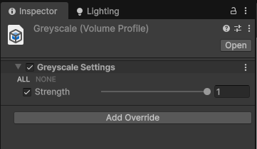
For this, let’s create a new volume profile using Create -> Rendering -> Volume Profile, and name it Greyscale. In the Inspector, we can add a list of overrides using this little button, so choose Basics -> Greyscale.
Then, we can go to GameObject -> Volume -> Global Volume (for an effect that’s active everywhere) or GameObject -> Volume -> Box Volume (for an effect which is only active when the camera is inside the attached box collider), and drag our profile onto the Volume Profile slot. We can edit the profile directly here, but be warned that it will modify the base profile if you’re sharing one profile between multiple volumes.
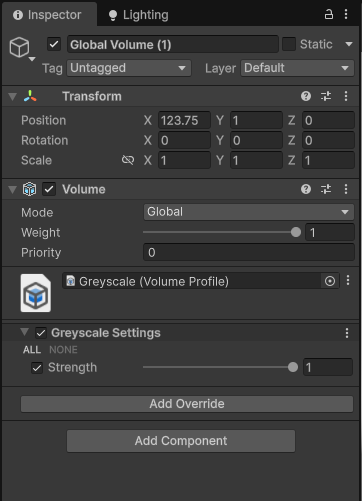
The effect starts off inactive, but we can tick the little box next to Strength to enable changing its value, and raise it above 0 and… nothing happens. We still need to add the effect to the Renderer Features list. If at any time in the future you have a volume-based post process effect which isn’t working, this is possibly the issue.
Find your Universal Renderer Data asset, which is probably in the Settings folder. It’s the same place we added the x-ray effect a few tutorials ago! Then, click Add Renderer Feature at the bottom and choose Greyscale. If all is well, the screen will turn greyscale as you increase the slider on the volume profile.
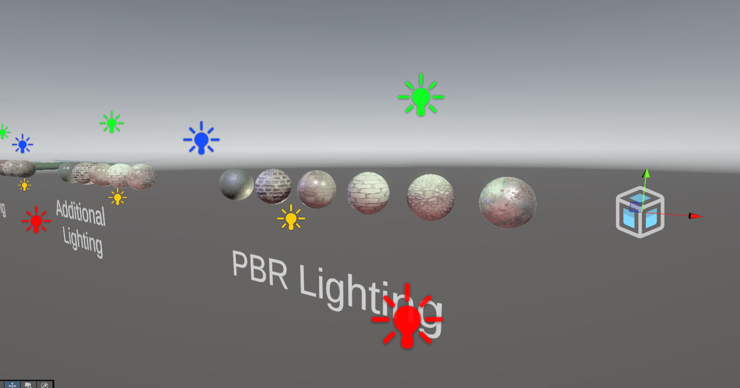
This should give you enough to start making any simple color modification post process effect, but I want to go further.
Subscribe to my Patreon for perks including early access, your name in the credits of my videos, and bonus access to several premium shader packs!
Silhouette Post Process
Sometimes, your effect needs access to the depth texture too. Remember when we used the depth texture in a silhouette shader attached to a mesh? Well, now we’re going to make a new version as a post process.
Most of the content of the two Greyscale scripts and the shader we just wrote can just be copied over to form the basis of the Silhouette scripts. In fact, I just copied and renamed the GreyscaleSettings and GreyscaleFeature scripts to new SilhouetteSettings and SilhouetteFeature scripts, and then replaced each instance of “Greyscale” with “Silhouette” in each script to give us a starting point.
Silhouette Settings
In the new SilhouetteSettings script, after renaming everything, let’s remove the strength variable since we no longer need it. One detail I didn’t mention is that any default values we specify here are the values that get used if there are no appropriate volumes with a Silhouette effect attached. With the Greyscale effect, we designed it such that the default strength of zero results in the effect not running, since IsActive would evaluate to false. We’ll do the same here.
I’m going to write the silhouette effect such that it’s either on at full strength or disabled completely, so I’ll add a BoolParameter called enabled, and set it to false by default. We can include check if this is true in IsActive. To make sure the effect starts off inactive by default, it’s not sufficient to just rely on the active variable which already exists and gets inherited from VolumeComponent, because active is true by default even when the SilhouetteFeature is attached to the Renderer Features list but no SilhouetteSettings exists on a volume anywhere.
using UnityEngine;
using UnityEngine.Rendering;

[System.Serializable, VolumeComponentMenu("Basics/Silhouette")]
public class SilhouetteSettings : VolumeComponent, IPostProcessComponent
{
    public BoolParameter enabled = new BoolParameter(false);

    ...

    public bool IsActive()
    {
        return enabled.value && active;
    }
}
Then, let’s add two ColorParameter variables to denote the color of the silhouette for objects at the camera’s near and far clip distances. It would be nice to have some control over the blending between these colors, so I’ll use a simple power function for it and include a ClampedFloatParameter bounded between 0 and, let’s say, 10.
public BoolParameter enabled = new BoolParameter(false);
public ColorParameter nearColor = new(Color.black);
public ColorParameter farColor = new(Color.white);
public ClampedFloatParameter depthPower = new(1.0f, 0.0f, 10.0f);
That’s the SilhouetteSettings sorted, so let’s move on to SilhouetteFeature.
Silhouette Renderer Feature
This is the same as GreyscaleFeature, with all mentions of “Greyscale” swapped to “Silhouette”. The stuff at the top (inside SilhouetteFeature but outside of the nested SilhouetteRenderPass) can stay as it is, but we’re actually going to gut the SilhouetteRenderPass a little.
Silhouette Render Pass
With the Greyscale effect, we cared about the original screen colors, but with the Silhouette effect, we only care about the values in the depth texture and we don’t need to know anything at all about the color texture – we’re just going to overwrite whatever is in it. That means we don’t need an intermediate copy texture or copy pass, so let’s delete those completely, and everything associated with them. It’s just one main pass now, which isn’t typical of post process effects.
class SilhouetteRenderPass : ScriptableRenderPass
{
    private Material material;

    public SilhouetteRenderPass()
    {
        profilingSampler = new ProfilingSampler("Silhouette Post Process");
        renderPassEvent = RenderPassEvent.AfterRenderingPostProcessing;
        requiresIntermediateTexture = false;
    }

    private void FindMaterial()
    {
        if (material != null) return;

        var shader = Shader.Find("Basics/PostProcess/Silhouette");
        material = new Material(shader);
    }

    private class MainPassData
    {
        public Material material;
        public TextureHandle inputTexture;
    }

    private static void ExecuteMainPass(RasterCommandBuffer cmd, MainPassData data)
    {
        Blitter.BlitTexture(cmd, data.inputTexture, new Vector4(1, 1, 0, 0), data.material, 0);
    }

    public override void RecordRenderGraph(RenderGraph renderGraph, ContextContainer frameData)
    {
        FindMaterial();

        ...
    }
}
Near the start of the RecordRenderGraph method, we need to ensure that the depth texture is ready and available for use in this pass using a special method called ConfigureInput, passing in ScriptableRenderPassInput.Depth. If you need access to the normal texture or motion vector texture, you can find those in ScriptableRenderPassInput too – just add another call to ConfigureInput.
Next, we no longer have a _Strength variable, but instead we’re going to send the _NearColor, _FarColor, and _DepthPower to the shader with the appropriate material.SetXYZ methods, then we come to our main pass.
This blit is going to be a bit strange because we don’t actually care about which texture we’re blitting from, since the shader is just going to read directly from the depth texture using existing library functions. We still need to specify a texture, though, so let’s just say our source texture is the activeDepthTexture, then we’ll also make sure we can read from it with UseTexture. Otherwise, this pass looks a lot like the second pass we wrote in GreyscaleRenderPass.
public override void RecordRenderGraph(RenderGraph renderGraph, ContextContainer frameData)
{
    FindMaterial();
    ConfigureInput(ScriptableRenderPassInput.Depth);

    var resourceData = frameData.Get<UniversalResourceData>();

    var settings = VolumeManager.instance.stack.GetComponent<SilhouetteSettings>();
    material.SetColor("_NearColor", settings.nearColor.value);
    material.SetColor("_FarColor", settings.farColor.value);
    material.SetFloat("_DepthPower", settings.depthPower.value);

    using (var builder = renderGraph.AddRasterRenderPass<MainPassData>("Silhouette_MainPass", out var passData, profilingSampler))
    {
        passData.material = material;
        passData.inputTexture = resourceData.activeDepthTexture;

        builder.UseTexture(resourceData.activeDepthTexture, AccessFlags.Read);
        builder.SetRenderAttachment(resourceData.activeColorTexture, 0, AccessFlags.Write);

        builder.SetRenderFunc(static (MainPassData data, RasterGraphContext context) =>
            ExecuteMainPass(context.cmd, data));
    }
}
That’s it for the changes to SilhouetteFeature, so let’s move on to the Silhouette shader, which is also copied from the Greyscale shader as a base.
Silhouette Shader
After renaming it at the top, let’s change which include files we need. We’ll no longer need the Color.hlsl file, but we do need DeclareDepthTexture.hlsl, which we used in the Silhouette shader we wrote for meshes in a previous tutorial. Then, let’s declare each of the variables we added to SilhouetteSettings, which we need in the fragment shader function.
In the frag function, let’s erase everything we wrote previously, then sample the depth texture using the SampleSceneDepth library function. We can use Linear01Depth to linearize these values between the near and far camera planes, then raise that value to the _DepthPower variable using the built-in HLSL pow function. Finally, we can lerp between the _NearColor and _FarColor, and that’s the shader done!
Shader "Basics/PostProcess/Silhouette"
{
    SubShader
    {
        Tags
        {
            "RenderPipeline" = "UniversalPipeline"
        }

        Pass
        {
            ZTest Always
            Cull Off
            ZWrite Off

            HLSLPROGRAM
            #pragma vertex Vert
            #pragma fragment frag

            #include "Packages/com.unity.render-pipelines.universal/ShaderLibrary/Core.hlsl"
            #include "Packages/com.unity.render-pipelines.core/Runtime/Utilities/Blit.hlsl"
            #include "Packages/com.unity.render-pipelines.universal/ShaderLibrary/DeclareDepthTexture.hlsl"

            float4 _NearColor;
            float4 _FarColor;
            float _DepthPower;

            float4 frag(Varyings i) : SV_Target
            {
                float rawDepth = SampleSceneDepth(i.texcoord);
                float linearDepth = Linear01Depth(rawDepth, _ZBufferParams);

                float depth = pow(linearDepth, _DepthPower);

                return lerp(_NearColor, _FarColor, depth);
            }

            ENDHLSL
        }
    }
}
In the Unity Editor, we can add a Silhouette effect to a volume, and crucially add the Silhouette feature to the Renderer Features list, then go back to the volume profile and click the enable button to make the silhouette render.
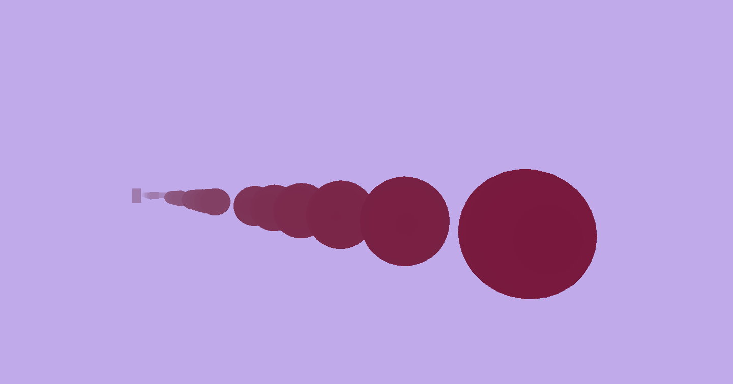
The power slider lets us tweak the mix between colors nicely, so play with it until you find a value you like.
Subscribe to my Patreon for perks including early access, your name in the credits of my videos, and bonus access to several premium shader packs!
Outline Post Process
Let’s go for the hat-trick and squeeze out one last post process shader in this video.
So far, we have just replaced each pixel of the screen with a different color based on existing information about that same pixel, but some effects need to consider adjacent pixels, such as an outline effect. It checks nearby pixels and if their color is significantly different from the current pixel color, then we can consider that pixel as existing on an ‘edge’ and draw an outline over it.
Outline Settings
I’ll go ahead and copy the greyscale scripts and shader again, renaming them to “Outline” instead of “Greyscale”. In the OutlineSettings script, we can keep the strength parameter, since it would be nice to make the outlines subtle by blending them only slightly onto the original image, and on top of that let’s add an outlineColor parameter, and a colorThreshold parameter, which lets us control how sensitive the shader is when detecting edges. Essentially, the higher this value, the bigger color difference there needs to be for a pixel to be considered an ‘edge pixel’.
using UnityEngine;
using UnityEngine.Rendering;

[System.Serializable, VolumeComponentMenu("Basics/Outline")]
public class OutlineSettings : VolumeComponent, IPostProcessComponent
{
    public ClampedFloatParameter strength = new(0.0f, 0.0f, 1.0f);
    public ColorParameter outlineColor = new(Color.black);
    public ClampedFloatParameter colorThreshold = new(0.9f, 0.0f, 1.0f);

    public bool IsActive()
    {
        return strength.value > 0.0f && active;
    }
}
Outline Renderer Feature
Over in OutlineFeature, practically everything can be kept the same from the Greyscale script after renaming: we need to overlay the outlines onto the original screen image, so we need the initial copy color pass. The only real difference is that we need to send a couple more parameter values to the shader after _Strength, namely _OutlineColor and _ColorThreshold.
using UnityEngine;
using UnityEngine.Rendering;
using UnityEngine.Rendering.RenderGraphModule;
using UnityEngine.Rendering.Universal;

public class OutlineFeature : ScriptableRendererFeature
{
    private OutlineRenderPass pass = new();

    public override void Create()
    {
        name = "Outline";
    }

    public override void AddRenderPasses(ScriptableRenderer renderer, ref RenderingData renderingData)
    {
        var settings = VolumeManager.instance.stack.GetComponent<OutlineSettings>();

        if (settings != null && settings.IsActive())
        {
            renderer.EnqueuePass(pass);
        }
    }

    class OutlineRenderPass : ScriptableRenderPass
    {
        private Material material;

        public OutlineRenderPass()
        {
            profilingSampler = new ProfilingSampler("Outline Post Process");
            renderPassEvent = RenderPassEvent.AfterRenderingPostProcessing;
            requiresIntermediateTexture = true;
        }

        private void FindMaterial()
        {
            if (material != null) return;

            var shader = Shader.Find("Basics/PostProcess/Outline");
            material = new Material(shader);
        }

        private static RenderTextureDescriptor GetCopyPassDescriptor(RenderTextureDescriptor descriptor)
        {
            descriptor.msaaSamples = 1;
            descriptor.depthBufferBits = (int)DepthBits.None;
            return descriptor;
        }

        private class CopyPassData
        {
            public TextureHandle inputTexture;
        }

        private class MainPassData
        {
            public Material material;
            public TextureHandle inputTexture;
        }

        private static void ExecuteCopyPass(RasterCommandBuffer cmd, CopyPassData data)
        {
            Blitter.BlitTexture(cmd, data.inputTexture, new Vector4(1, 1, 0, 0), 0.0f, false);
        }

        private static void ExecuteMainPass(RasterCommandBuffer cmd, MainPassData data)
        {
            Blitter.BlitTexture(cmd, data.inputTexture, new Vector4(1, 1, 0, 0), data.material, 0);
        }

        public override void RecordRenderGraph(RenderGraph renderGraph, ContextContainer frameData)
        {
            FindMaterial();

            var resourceData = frameData.Get<UniversalResourceData>();
            var cameraData = frameData.Get<UniversalCameraData>();

            var colorCopyDescriptor = GetCopyPassDescriptor(cameraData.cameraTargetDescriptor);
            var colorCopy = UniversalRenderer.CreateRenderGraphTexture(renderGraph, colorCopyDescriptor,
                "_OutlineColorCopy", false);

            var settings = VolumeManager.instance.stack.GetComponent<OutlineSettings>();
            material.SetFloat("_Strength", settings.strength.value);
            material.SetColor("_OutlineColor", settings.outlineColor.value);
            material.SetFloat("_ColorThreshold",  settings.colorThreshold.value);

            using (var builder = renderGraph.AddRasterRenderPass<CopyPassData>("Outline_CopyColor", out var passData, profilingSampler))
            {
                passData.inputTexture = resourceData.activeColorTexture;

                builder.UseTexture(resourceData.activeColorTexture, AccessFlags.Read);
                builder.SetRenderAttachment(colorCopy, 0, AccessFlags.Write);

                builder.SetRenderFunc(static (CopyPassData data, RasterGraphContext context) =>
                    ExecuteCopyPass(context.cmd, data));
            }

            using (var builder = renderGraph.AddRasterRenderPass<MainPassData>("Outline_MainPass", out var passData, profilingSampler))
            {
                passData.material = material;
                passData.inputTexture = colorCopy;

                builder.UseTexture(colorCopy, AccessFlags.Read);
                builder.SetRenderAttachment(resourceData.activeColorTexture, 0, AccessFlags.Write);

                builder.SetRenderFunc(static (MainPassData data, RasterGraphContext context) =>
                    ExecuteMainPass(context.cmd, data));
            }
        }
    }
}
Outline Shader
Now let’s move onto the shader. At the top, rename it to Basics/PostProcess/Outline, and then we can remove the Color.hlsl include file since we don’t need it. Let’s throw in the extra two shader variables here: _OutlineColor and _ColorThreshold.
Shader "Basics/PostProcess/Outline"
{
    SubShader
    {
        Tags
        {
            "RenderPipeline" = "UniversalPipeline"
        }

        Pass
        {
            ZTest Always
            Cull Off
            ZWrite Off

            HLSLPROGRAM
            #pragma vertex Vert
            #pragma fragment frag

            #include "Packages/com.unity.render-pipelines.universal/ShaderLibrary/Core.hlsl"
            #include "Packages/com.unity.render-pipelines.core/Runtime/Utilities/Blit.hlsl"

            float _Strength;
            float3 _OutlineColor;
            float _ColorThreshold;

            float4 frag(Varyings i) : SV_Target
            {
                ...
            }

            ENDHLSL
        }
    }
}
Then, we come to the frag shader function. After we get the original screen color, let’s remove the rest of the code, and have a think about how to detect differences in color between adjacent pixels. I’m going to use one of the simplest approaches with the Roberts Cross operator: the current pixel is the bottom-left in a 2x2 grid, then we take a gradient across the pixel colors of the bottom left to top right diagonal, and another gradient from top left to bottom right, do a little trigonometry to get an overall gradient, and check if that gradient exceeds the threshold variable.
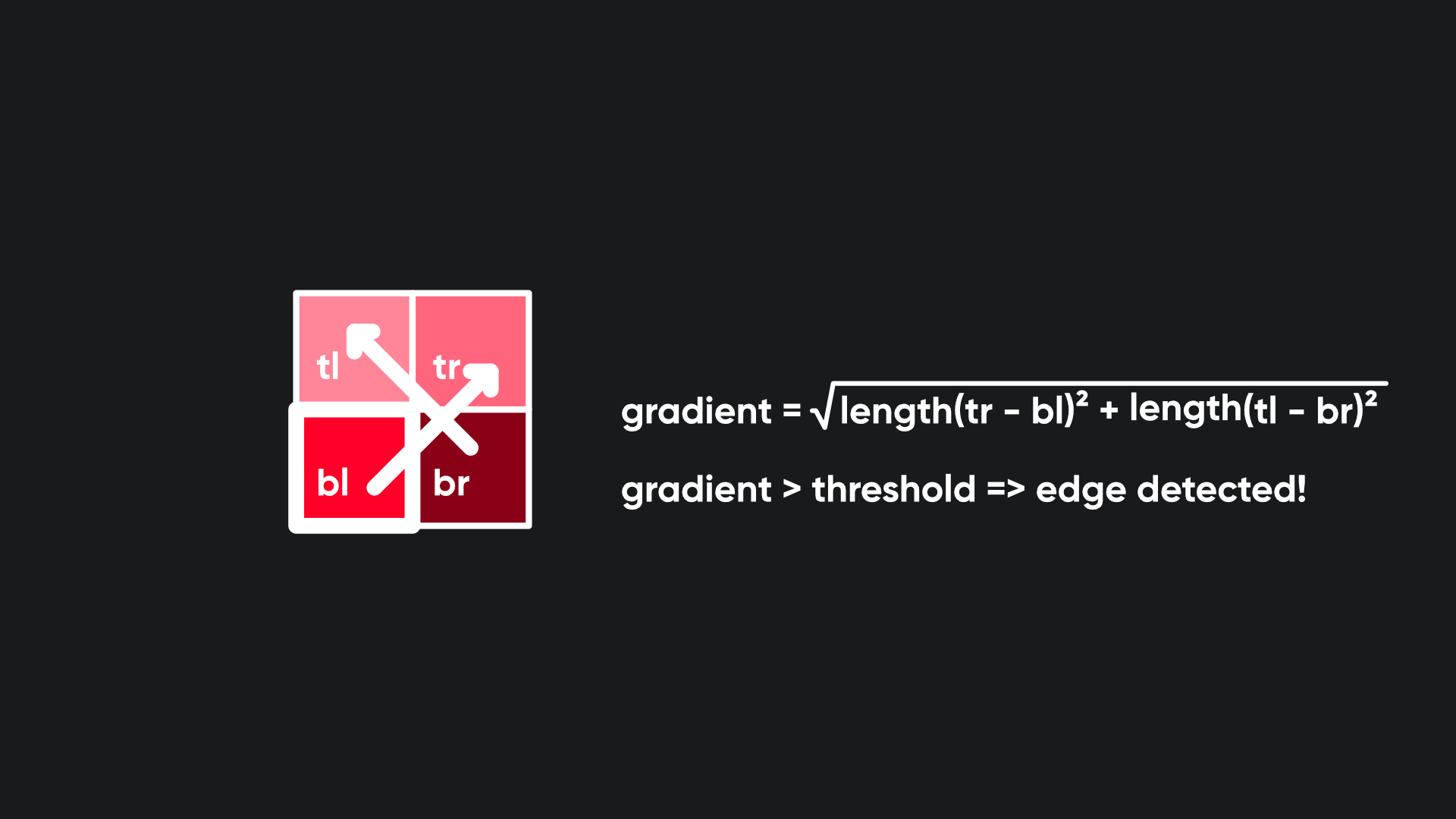
Let’s first get four new sets of UV coordinates for the four extra texture samples. We can do that by taking the base UVs and then using _BlitTexture_TexelSize to add a pixel-width offset in the direction we want. The _TexelSize variable’s xy components store 1/width and 1/height respectively, which happens to be the UV offset required to hop over to the adjacent pixel, so let’s use that for each of the four UVs.
float4 originalColor = SAMPLE_TEXTURE2D(_BlitTexture, sampler_PointClamp, i.texcoord);

float2 blUV = i.texcoord + float2(0.0f, 0.0f);
float2 trUV = i.texcoord + float2(_BlitTexture_TexelSize.x, _BlitTexture_TexelSize.y);
float2 brUV = i.texcoord + float2(_BlitTexture_TexelSize.x, 0.0f);
float2 tlUV = i.texcoord + float2(0.0f, _BlitTexture_TexelSize.y);

float3 col0 = SAMPLE_TEXTURE2D(_BlitTexture, sampler_LinearClamp, blUV).rgb;
float3 col1 = SAMPLE_TEXTURE2D(_BlitTexture, sampler_LinearClamp, trUV).rgb;
float3 col2 = SAMPLE_TEXTURE2D(_BlitTexture, sampler_LinearClamp, brUV).rgb;
float3 col3 = SAMPLE_TEXTURE2D(_BlitTexture, sampler_LinearClamp, tlUV).rgb;

...
With those UVs, we can sample the original screen image four times, and then we can get the first gradient by subtracting the bottom-left sample from the top-right sample, and a second gradient by subtracting the bottom-right sample from the top-left sample. These gradients are still float3 values and they’re calculated per color channel.
float3 grad0 = col1 - col0;
float3 grad1 = col3 - col2;

...
Then, let’s use a little Pythagoras to get an overall gradient value. I want to collapse those float3 gradients into a float value, so we’ll get the squared magnitude of the first gradient using a neat trick where you take the dot product of the float3 with itself, and do the same with the second gradient, then get the square root of their sum, and that’s our overall gradient, representing “how edgy” this pixel is.
Next, let’s check if the edginess exceeds the threshold. If it does, great! Let’s set the edge value to the _Strength variable’s value. If not, let’s set it to 0 to say this is not an edge pixel.
float edge = sqrt(dot(grad0, grad0) + dot(grad1, grad1));
edge = edge > _ColorThreshold ? _Strength : 0.0f;

...
Finally, let’s use the lerp function to choose between the original screen color and the _OutlineColor variable, using that edge value as the interpolation factor, and set the output alpha to the original color’s alpha. And that’s it!
return float4(lerp(originalColor.rgb, _OutlineColor, edge), originalColor.a);
We can apply the outline filter to our volume, after remembering to add the outline effect to the Renderer Features list, and try playing around with the sensitivity and strength until we get an outline effect we like.
Being one of the simplest kinds of outline, it’s limited, but it does a quick and dirty job, and I got to show you some useful techniques you’ll probably use if you delve deeper into post process effects!
If you’re feeling a little ambitious, you could try adding other edge detection methods into this shader. For example, you could detect gradients in the depth texture and in the normal texture with different thresholds and add all the contributions together to get a better outline, and I think you have all the tools to do that! If you get stuck, I’ve thrown together an alternative shader creatively named Outline2 which does just that, and you can find it in the GitHub repository for this project.
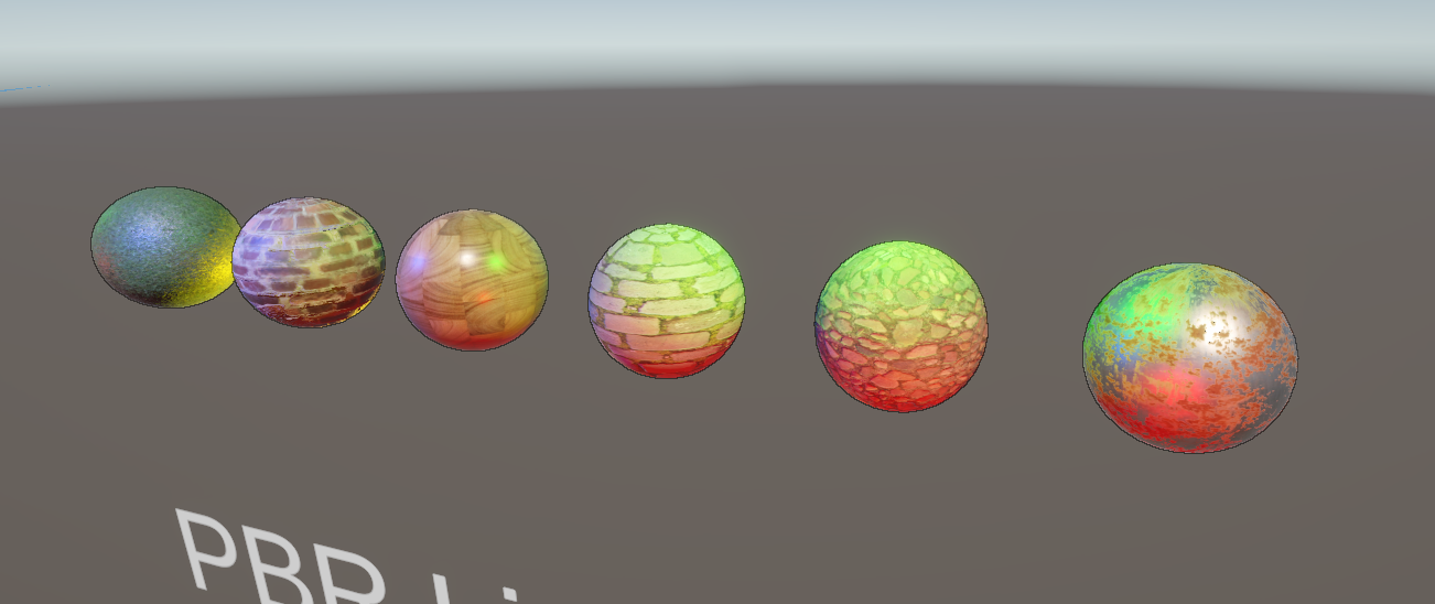
Until next time, have fun making shaders!
Subscribe to my Patreon for perks including early access, your name in the credits of my videos, and bonus access to several premium shader packs!