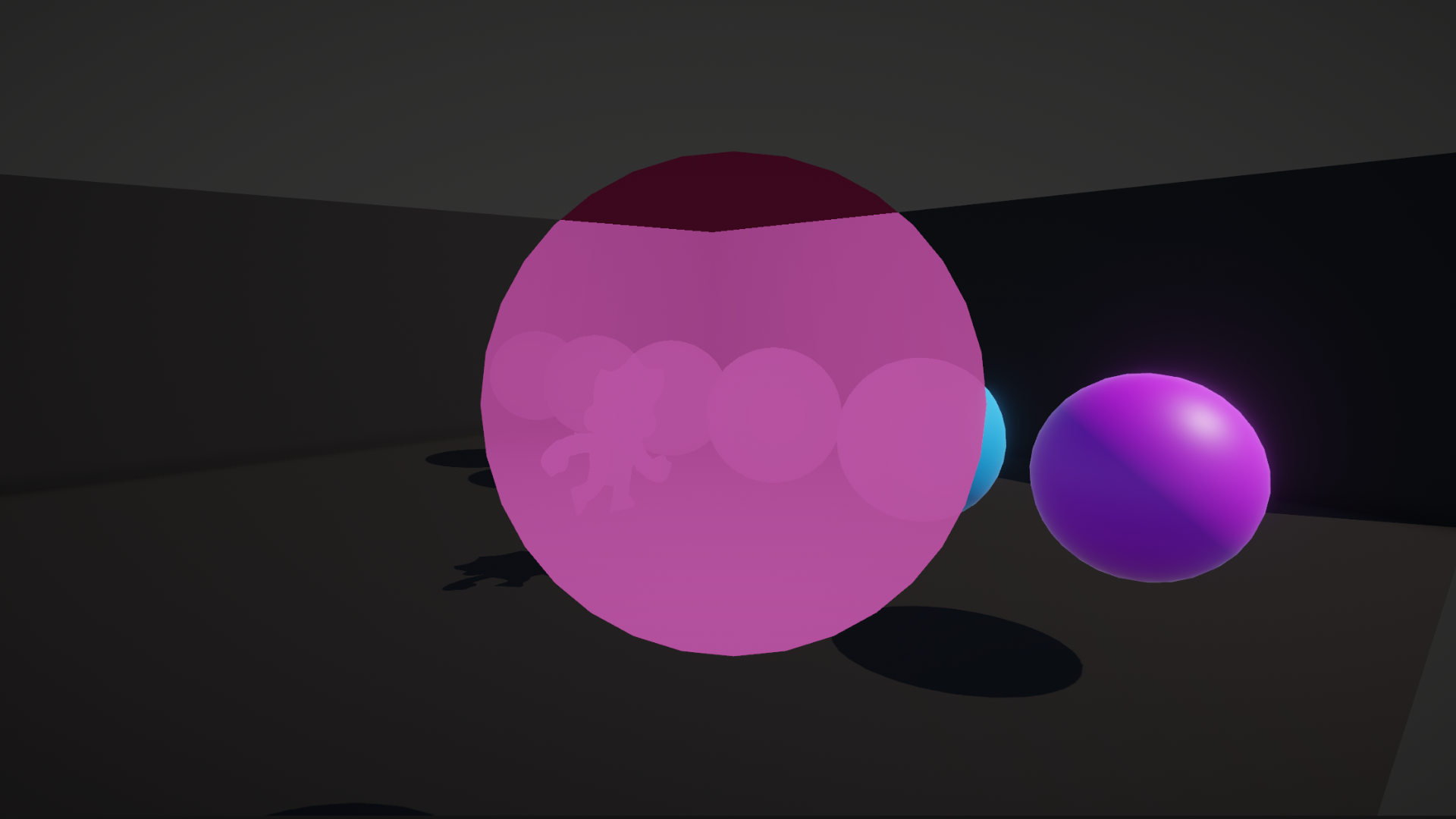
In Part 3, we saw how transparent rendering works in Shader Graph, and in this part, we will be exploring the depth buffer. Here is a silhouette that we will be creating later in this video:
Check out this tutorial over on YouTube too!
The Depth Buffer
In Part 3, I mentioned that we can skip over rendering parts of objects if we know something was already rendered in front of it. But how does the rendering pipeline know anything about the relative ordering of objects? In this example, the shaded region of the cube won’t be rendered because it is behind the wall:

Colors get rendered to the frame buffer, which is essentially an image with the same dimensions as your screen, and a shader’s job is to fill this buffer with color values. With this information alone, it is impossible to tell if we’re about to draw over a pixel when we’re not meant to, because the frame buffer contains no positional information. In the past, renderers carefully sorted all objects from back to front and rendered them in that order, but this approach cannot handle strange mesh shapes or partially obscured objects, because the entire mesh is drawn with the same ‘depth’ value. You get sorting issues.
That’s why modern renderers use a secondary buffer called the depth buffer, also known as the z-buffer. This is a second image which is the same size as the frame buffer, except it stores the distance between a pixel on an object and the camera. Well, not exactly - the way it stores values is quite complicated. Briefly, the depth buffer stores floating-point values between 0 and 1 along a non-linear curve, where more bits are prioritized for closer objects for added depth precision, because this is where it would otherwise be much easier to spot depth sorting errors. Don’t worry about the actual method Unity uses to store depth values, because Shader Graph gives us ways to decode the actual distances as we will see later.
Here is an example of a frame buffer on the left, and the corresponding depth buffer. The dotted region represents where the green sphere failed the depth test, and therefore didn’t overwrite depth buffer values:

All we need to know right now is that when we render something, we carry out these steps:
- Calculate the depth value of the pixel we are trying to draw.
- Compare this value with the depth value already in the depth buffer at this position. This is called depth testing.
- If the new pixel has a lower or equal depth value, replace the frame buffer color value with the new pixel color.
- Additionally, if the object we are drawing is opaque, replace the existing depth buffer value with the new pixel depth. Transparent objects usually don’t write their depth information.
These depth testing steps happen automatically partway through rendering an object - we don’t need to write any code or add any nodes to make it happen. Now that we know the basics of the depth buffer, let’s explore depth… in more depth.
Subscribe to my Patreon for perks including early access, your name in the credits of my videos, and bonus access to several premium shader packs!
Depth in Shader Graph
For this demonstration, I copied the ColorExample graph from Part 1 and named the new one “DepthExample”, but you can follow these steps with any basic graph. We are interested in the Graph Settings window, in particular the Depth Write and Depth Test options.
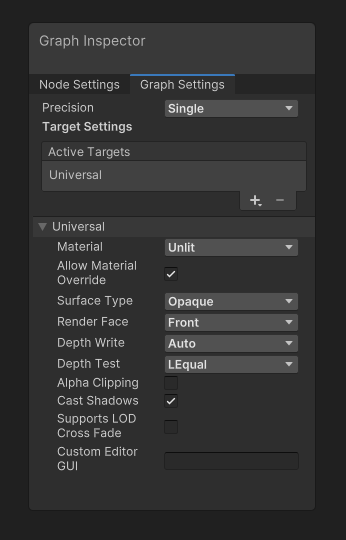
Depth Write lets you choose whether objects overwrite the depth buffer if the depth test was successful. By default, with the Auto option, opaques do write, and transparents do not. You can change it to ForceEnabled or ForceDisabled, but I’d usually leave it at Auto unless you have a very specific use case.
Depth Test is much more interesting, as it lets you pick which kind of comparison to use when attempting to write new pixels. The default behavior is LEqual, short for “Less or Equal”, which means the test passes if the new object is closer to or the same distance from the camera as the last object drawn at that pixel position.
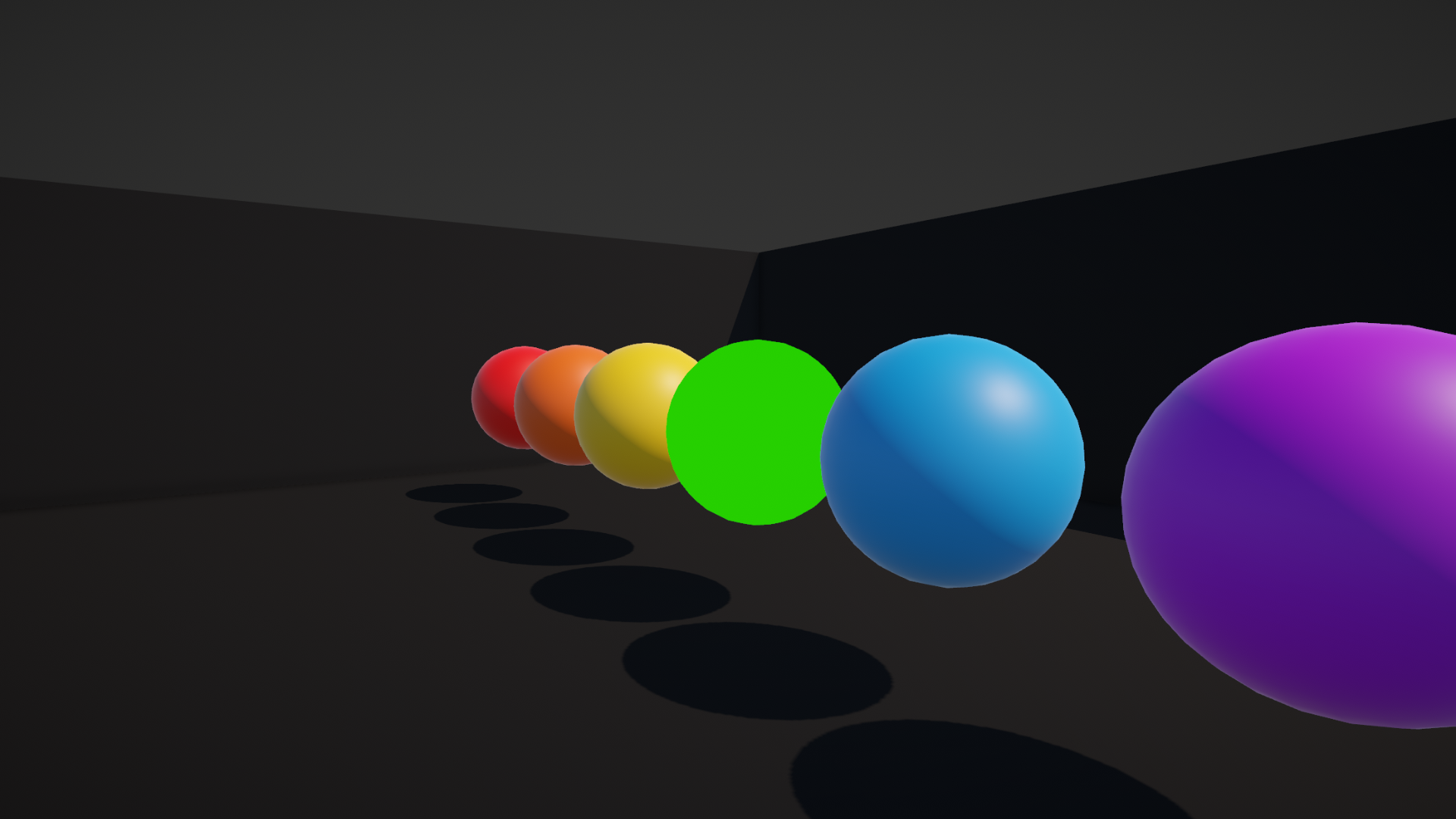
We can change it in many ways. The Always option passes the depth test no matter what the existing depth value is:
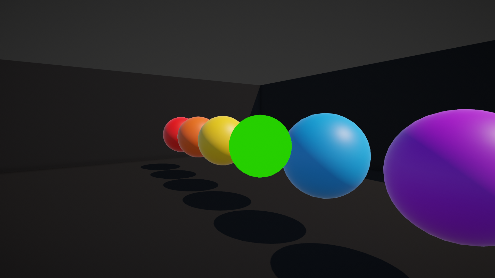
Never will fail ever time:
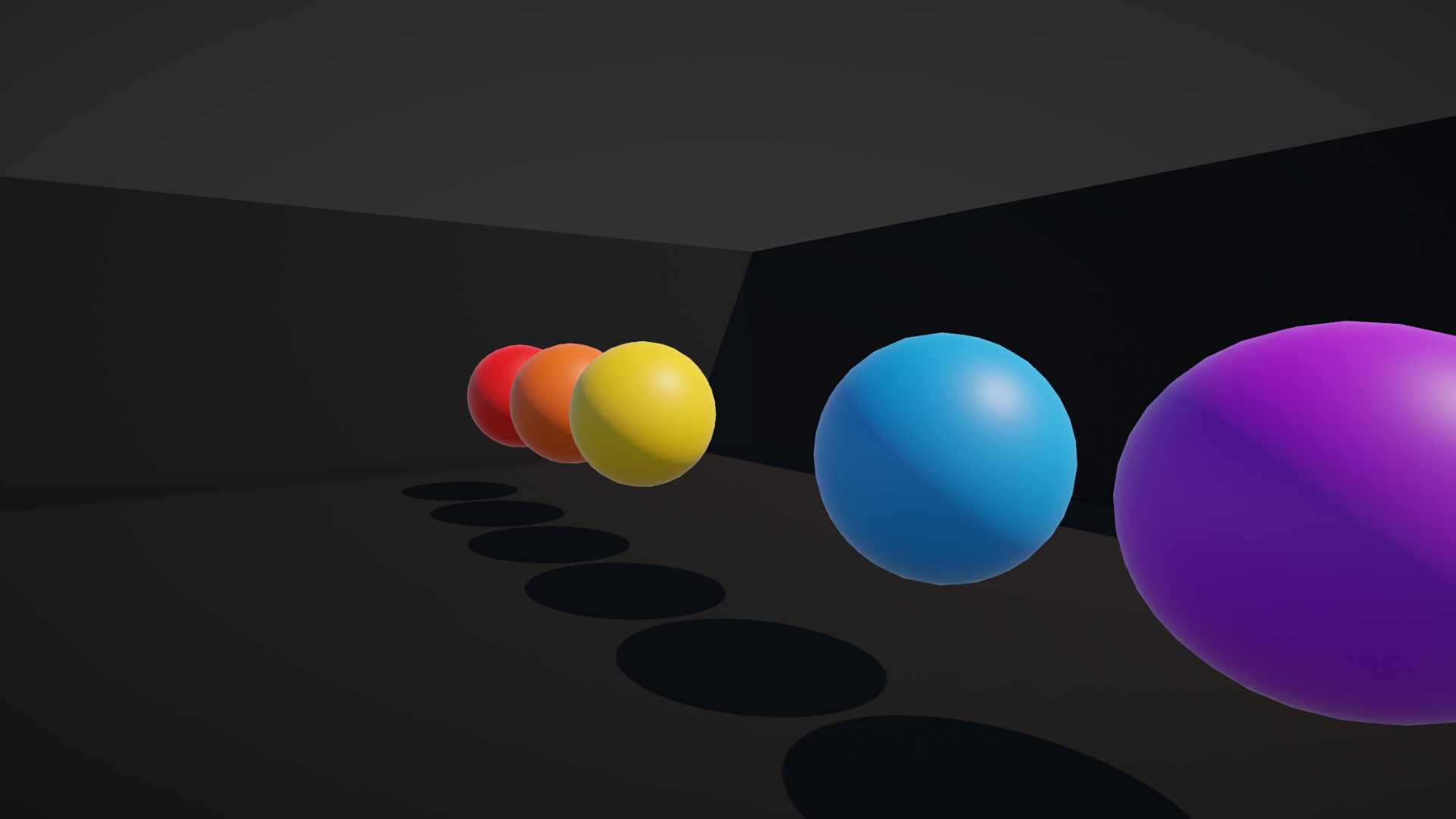
Greater will only pass if the new object is further away than the existing object:
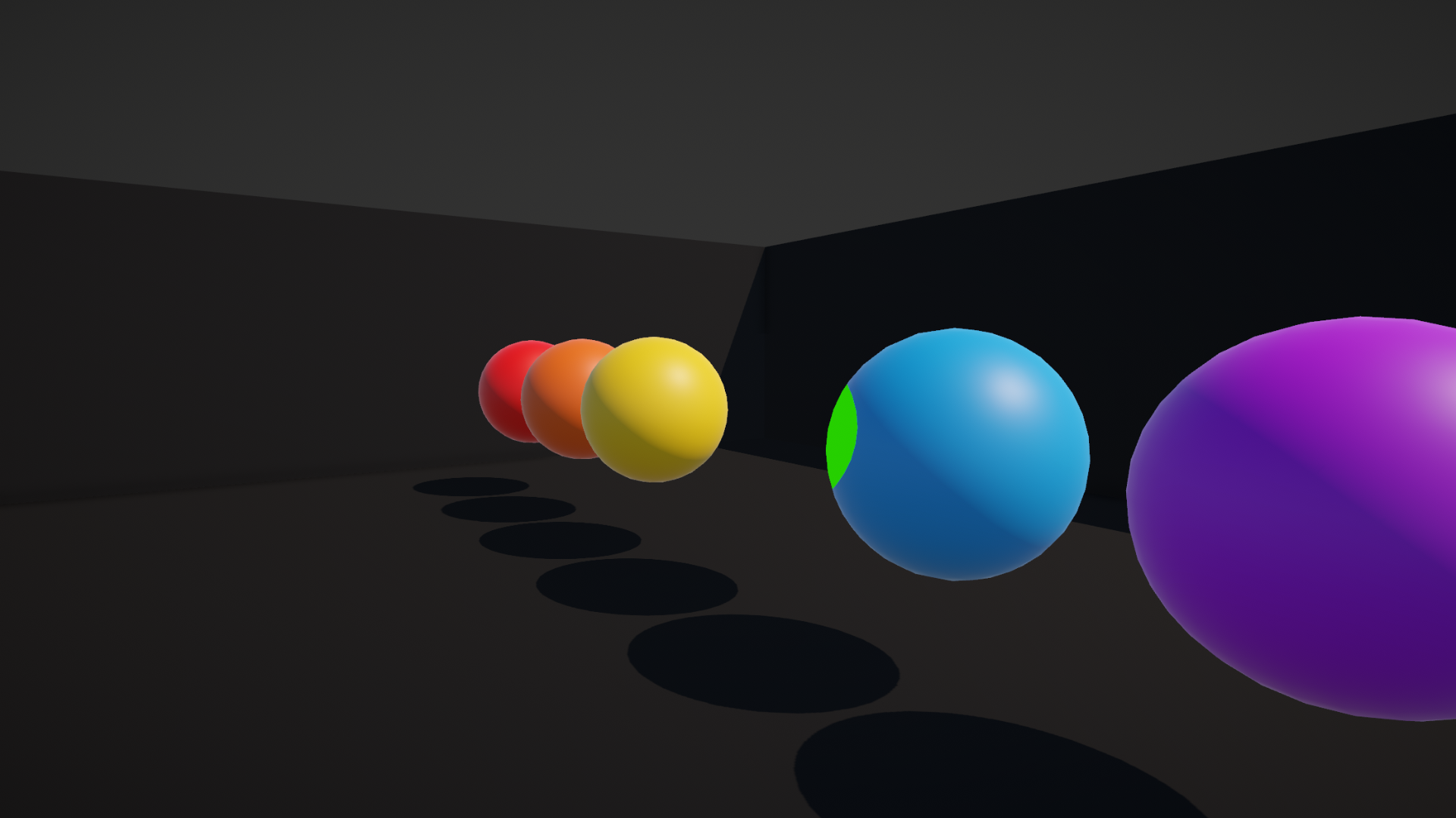
There are also Less, Equal, NotEqual, and GEqual options, which I’m sure you can work out. I’d encourage you to try out different options to see what they do! The Allow Material Override tickbox option in Graph Settings is especially useful here, as it lets you tweak these depth options on a per-material basis, rather than solely on a per-shader basis. Remember to hit Save Asset when you’re done making tweaks inside the graph.
It doesn’t feel like we have done much “shadery” work so far, so let’s explore another way of working with depth.
The Depth Texture
Since we store values in the depth buffer, you may be wondering if it’s possible to use those values inside a shader, and the answer is yes, but there are some restrictions. Our shaders can’t read the depth buffer directly. Instead, after all opaque objects have been drawn, Unity copies the state of the whole depth buffer into what’s called the camera depth texture, or just “depth texture” for short. This texture is accessible to our shaders. However, we should keep two things in mind: first, the texture only contains useful information if we’re writing a transparent shader.

Second, the texture will not contain any information about the depth of transparent objects.

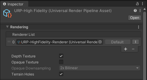
To use this texture in URP, we first need to enable it. This is another of those things I really want to drill into your brain, because you WILL forget this step in future projects. First, find the URP asset your project is using. If you created the project using the URP template, then this asset is in Assets/Settings. In fact, there will be three of them, and you should follow these steps for all three. Select each one, and tick the Depth Texture setting right at the top of the Inspector window.
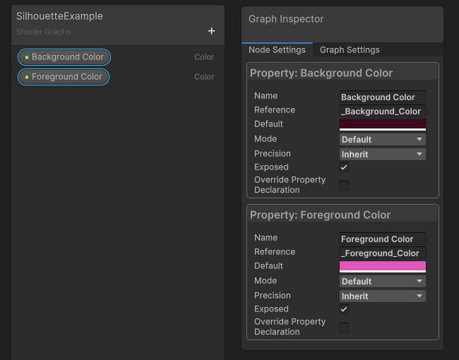
Now that we have set everything up, let’s make a Silhouette shader, which I’ll make from scratch via Create -> Shader Graph -> URP -> Unlit Shader Graph, and I’ll name it “SilhouetteExample”. First things first, go to the Graph Settings and change the Surface Type to Transparent. Then, I’ll add two new Color properties: one called Foreground Color and the other called Background Color. Just make sure their default values are distinct.
Next, add a node called Scene Depth. By default, this node samples the depth texture using the screen coordinate of the current pixel being rendered, so we don’t need to worry about inputting anything to the node. It has a little drop-down menu with three options:
The Raw option grabs the depth value and does no changes to it. This is the weird, non-linear value I talked about previously, and it is between 0 and 1.
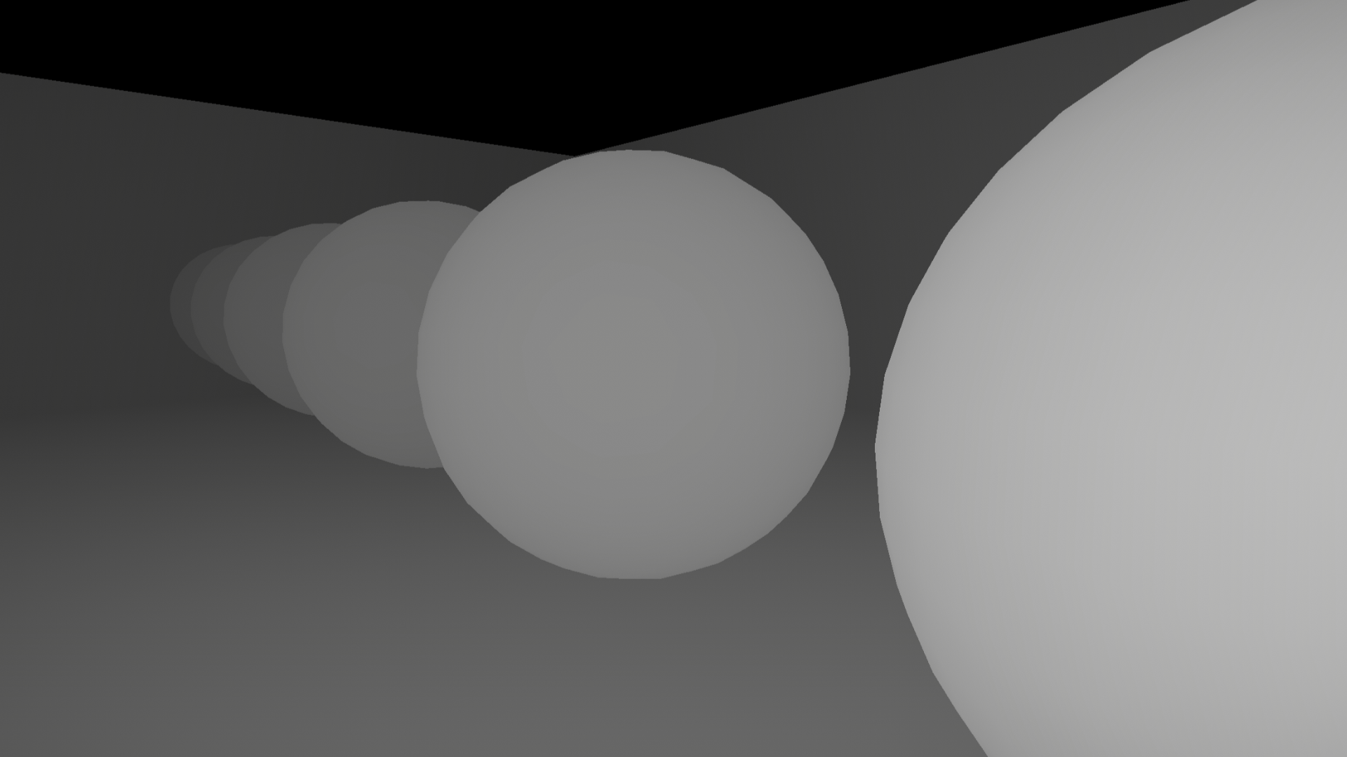
The Linear01 option linearizes the depth value, and it is also between 0 and 1. Being “linear” in this context means an object that is twice as far away will have twice the depth value, which does not happen in Raw mode. For some reason, the values run in the opposite direction, too.
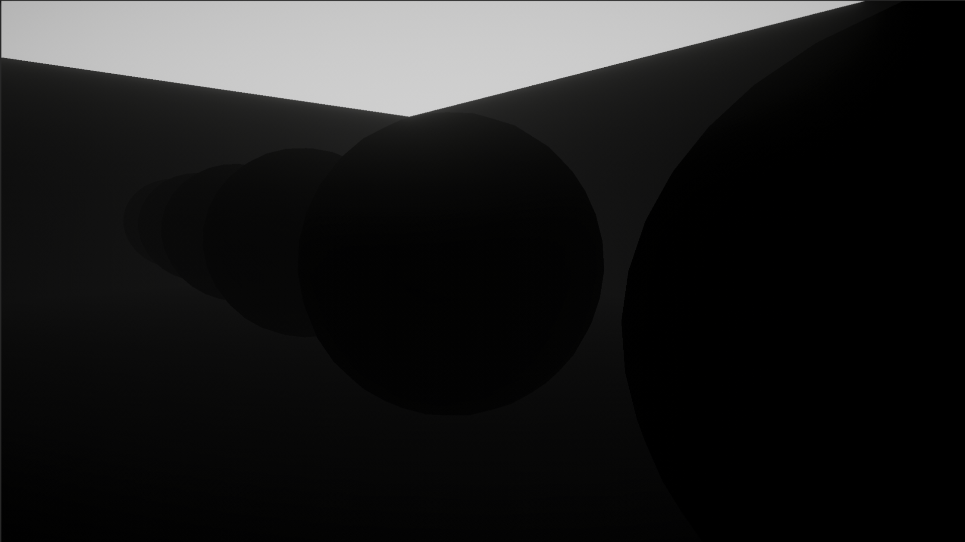
The Eye option converts depth values to distances in world space units, basically meters, from the camera. It’s useful for some effects.

For a silhouette effect, Linear01 is actually perfect.
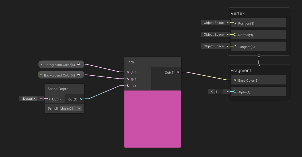
Next, I’m going to add a Lerp node to my graph. “Lerp” is short for “Linear Interpolation”, which is a fancy term which just means I’m going to blend or mix between two values. The A and B inputs are the two values getting mixed, and the T input is how far along between A and B we are on a straight line. T should be between 0 and 1, so when T is 0.25, it means we mix 75% of A and 25% of B.

As you might have guessed, we can plug the Scene Depth output into the T slot, and then plug the Foreground and Background colors into the A and B slots respectively. Finally, we can slot the Lerp output into the Base Color output block, hit Save Asset, and come back to the Scene View.
I’m going to place a sphere with my silhouette material in front of a few objects and see what it looks like in the Game View.
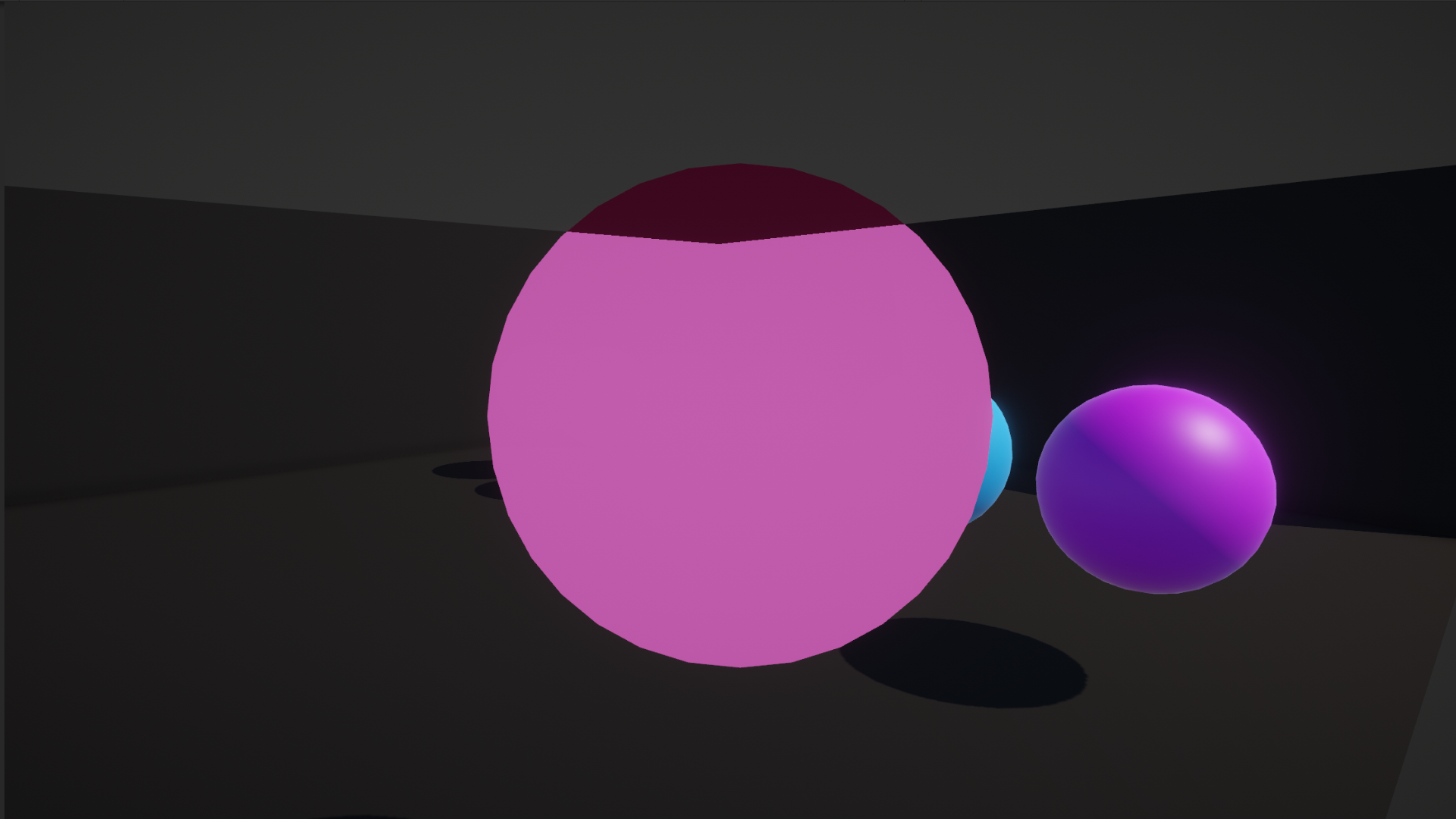
Here, I can’t really discern some of the scene objects, and that’s because the far clip plane of the camera is 1000 by default, so the 0 to 1 depth range is stretched over 1000 world space units.
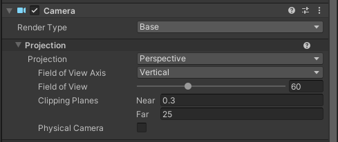
If we reduce this value massively to something like 20, we should see the difference more clearly.

Conclusion
We have learned how the depth buffer makes it possible to render objects in the correct order, and we used the camera depth texture to display a silhouette effect. Tune in next time to find out how vertex shaders can be used to manipulate the position of objects on-screen. Thanks for reading!
Subscribe to my Patreon for perks including early access, your name in the credits of my videos, and bonus access to several premium shader packs!
Acknowledgements
Special thanks to my Patreon backers for Sep - Nov 2023!
JP SungHoon Kang Verisutha Jack Dixon Morrie Mr.FoxQC Josh Swanson Leonard pixel_Wing Alexis Lessard beany claudio croci dmitrii-t Hassan Karouni Jau Liu Jun Mikel Bulnes Ming Lei Muhammad Azman Olly J Paul Froggatt Ray J Will Poillion Zachary Alstadt 源 刘
