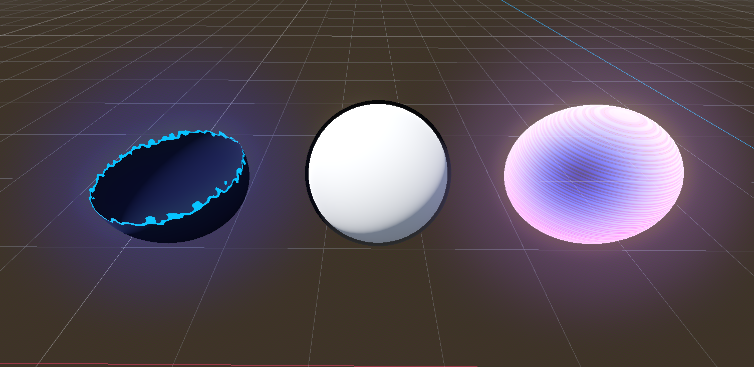
I finally tried out Godot. In classic Dan fashion, I started my journey by looking at Godot’s shader capabilities. On the surface, it’s not too far from Unity’s offering: code-based shaders (with GLSL instead of HLSL), a visual shader editor tool, in 2D and 3D, supporting custom post process effects, tessellation, and compute shaders. But I wanted to see how the typical shader experience differs between the engines. In this tutorial-slash-opinion piece, I find out just that.
Check out this tutorial over on YouTube too!
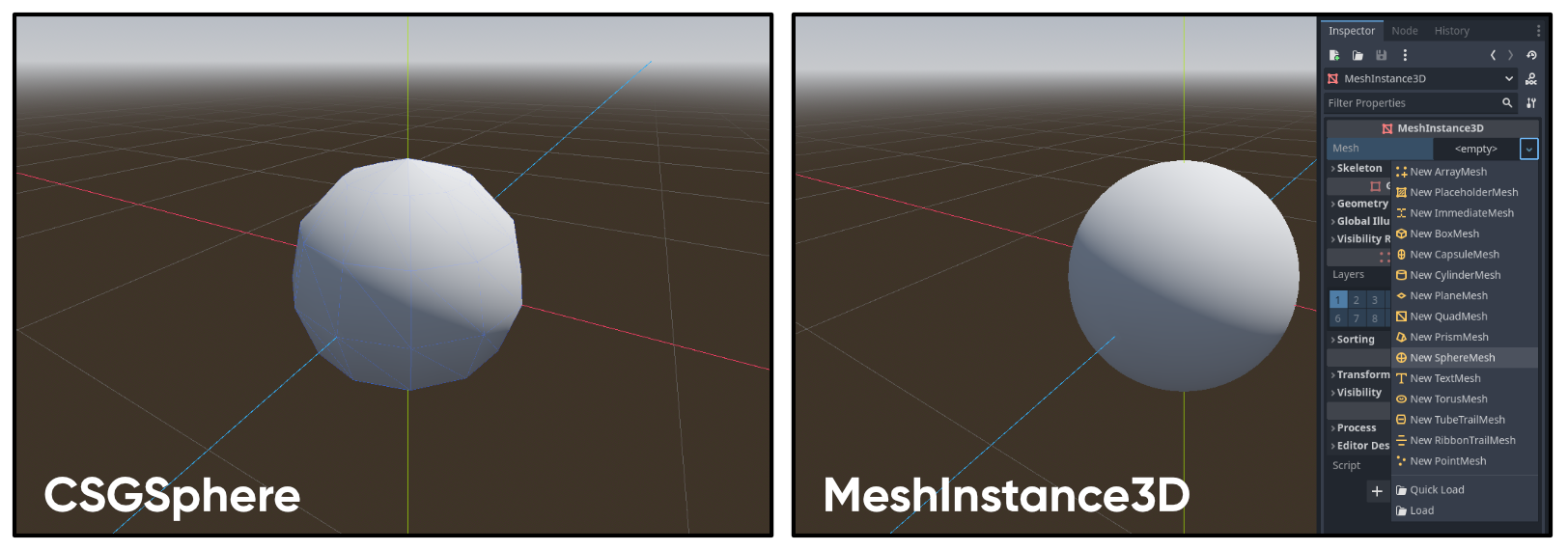
As a beginner, my first stumble was in adding a test sphere to my scene. I kept adding a CSGSphere node, but you’re meant to add a MeshInstance3D node and then pick a sphere mesh from its options. Much better. In Unity, you have the concept of ‘scenes’ and ‘prefabs’, but in Godot, both concepts are covered by ‘scenes’, as you can drag scenes into other scenes. For each shader I worked on, I opened a fresh scene, added a sphere mesh, then I have one master scene containing instances of all those sub-scenes. Those sub-scenes are like Unity prefabs. I’m also using Godot 4.2.1.
Dissolve Effect
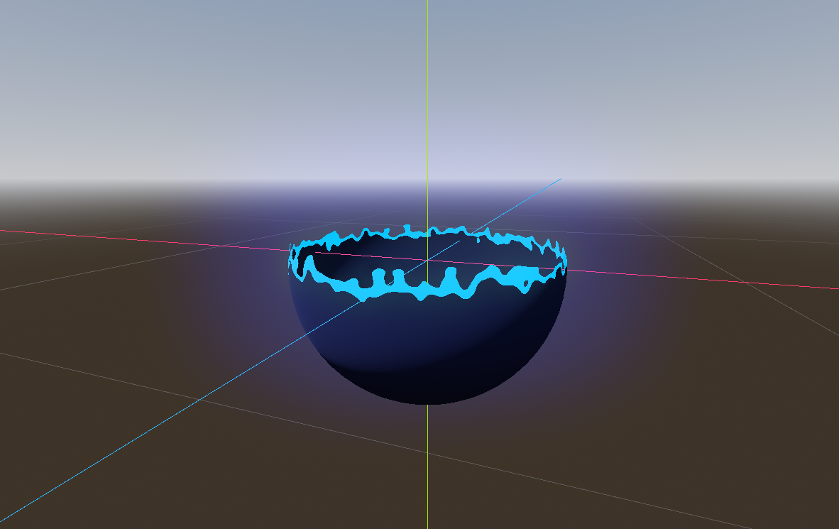
I figured the best approach would be to create shaders I’ve made in Unity before, so I started with the Dissolve effect, which seems to have become the “Hello, World” of visual shaders. The premise is simple: cut off parts of the mesh based on its world-space height, add some noise to modulate the shape of the edge, and then make the edges glow. I like this shader because it’s relatively simple, but it covers a lot of shader topics.
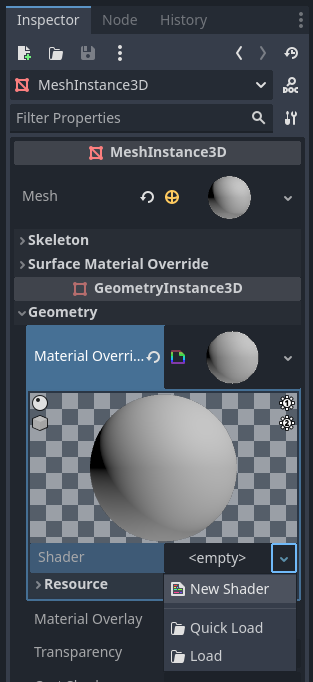
I created a new ShaderMaterial on my sphere in the Geometry dropdown, then I clicked on the material, where I’m able to add a new shader.
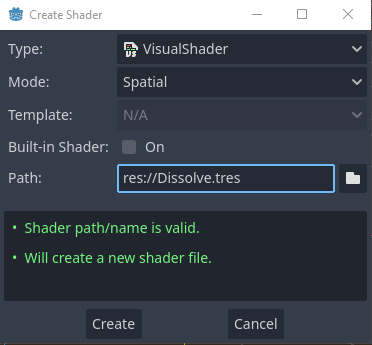
I chose VisualShader as the type - this is Godot’s answer to Unity’s Shader Graph - and I named it “Dissolve”. The graph environment looks a lot like Shader Graph, with the outputs in the middle in a big list, although Godot seems to forever list them all and I’m not sure if there’s a way to hide any of them.
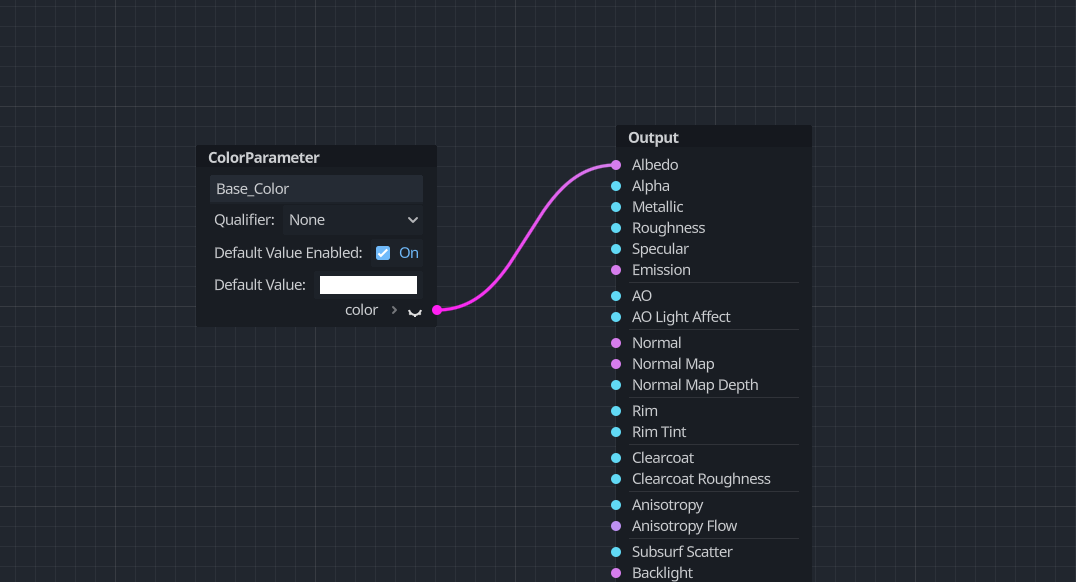
Unlike in Unity, we declare shader properties/parameters in the middle of the graph, rather than in a menu on the side. With that in mind, let’s right-click to open the Add Node window and find ColorParameter in the list, which you can do by typing its name in the search bar. On this new node, we can name the parameter whatever we want in the text field, although Godot removes special characters and replaces whitespace with underscores. We can also use the tickbox to set a default value. I’m going to name the parameter “Base Color” and connect it to the graph’s Albedo output, which is like the basic color of the object before lighting gets applied.
Now let’s implement a height-based cutoff. To do this, we need to connect some value to both the Alpha and Alpha Scissor Threshold graph outputs. Each pixel whose Alpha value is lower than its Alpha Scissor Threshold will be culled. I’ll add a FloatConstant to the graph, set it to a value of 0.5, and connect it to Alpha Scissor Threshold (in a moment, we’re going to be outputting 1s or 0s to Alpha).

Now, if we right-click to find the node to get the world-space position of the current pixel on the mesh, we’ll swiftly discover there isn’t one. There are a few deceptively closely-named nodes which don’t do what we want. We have to set up this data ourselves.

Using the dropdown in the top-left corner of the window, I can swap the graph view from Fragment mode, which operates on each pixel, to Vertex mode, which operates on the mesh’s vertices.
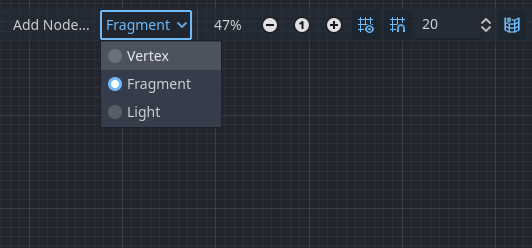
This section of the graph allows us to do stuff like animate the shape of the mesh, but I’m going to use it to calculate the world-space position and just pass the data along to the fragment stage. It’s an expensive operation involving a matrix multiplication, so I want to do it here instead of inside the fragment stage, because we typically have far fewer vertices on a mesh than pixels covered by that mesh.
In shader terminology, this kind of data is called “varying” because it varies - changes - between the vertex and fragment stages. If we click the Manage Varyings button, and then Add Varying, we can create a Vector3 called “WorldPos”.

Now, we can add a VaryingSetter node to our graph and find our WorldPos varying from the dropdown - this is basically an extra graph output.
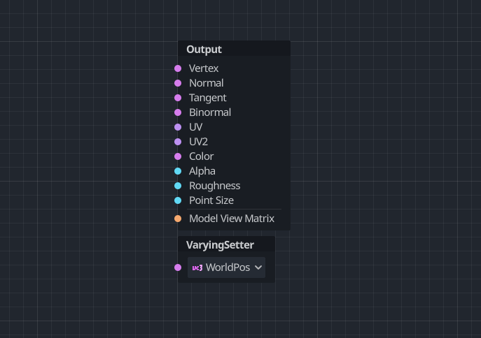
To calculate the world position, we need to take the object-space position of the vertex through the aptly-named Vertex node and multiply it with the model matrix (using the Model node), which is the transformation that changes positions defined relative to a mesh (object space) into positions relative to the scene the mesh exists in (world space). To actually perform the calculation, we use a node called TransformVectorMult, then we can connect its output to the WorldPos VaryingSetter node.

Look, I know that not everything is gonna work the same way as in Unity, but like, world position is just one node in Shader Graph! Godot’s workflow is actually super close to how it works in code-based shaders, where you need to do this stuff manually in the vertex shader. But I feel as though these tools should handle this type of work for you behind the scenes, y’know?
Anyway, let’s head back over to the Fragment section of the graph, add a VaryingGetter node to get our WorldPos, click the tiny arrow on the right to split the vector into its components, and drag the Y component into the Alpha output. The node says RGB, but it corresponds to XYZ. Then, after you discover this causes a bug in the Godot version I was using, instead, you close up the arrow and drag the whole vector into a Vector3Decompose node and take the Y component from that instead. It’s doing the same thing, so I’m not sure why the other approach was bugged. Oh well, hopefully it’s fixed in the future. With this setup, Godot will cut off all pixels whose y-position is below 0.5 (we hard-coded that value into).

Let’s make this a bit more customizable. I’m going to add another FloatParameter and name it “Dissolve Height”, which is going to be the height at which pixels get culled. Then, I will add a node called Step and connect my new Dissolve Height parameter to the Edge slot and the y-position into the X slot. What the Step node does is compare the two inputs, and if X is higher than Edge, it outputs 1, otherwise it outputs 0. What we’re doing here is saying “output 1 if the pixel is higher than the Dissolve Height.” I want my dissolve to work in the opposite direction, so I’m going to use a One Minus node to reverse the output, and connect it to Alpha.

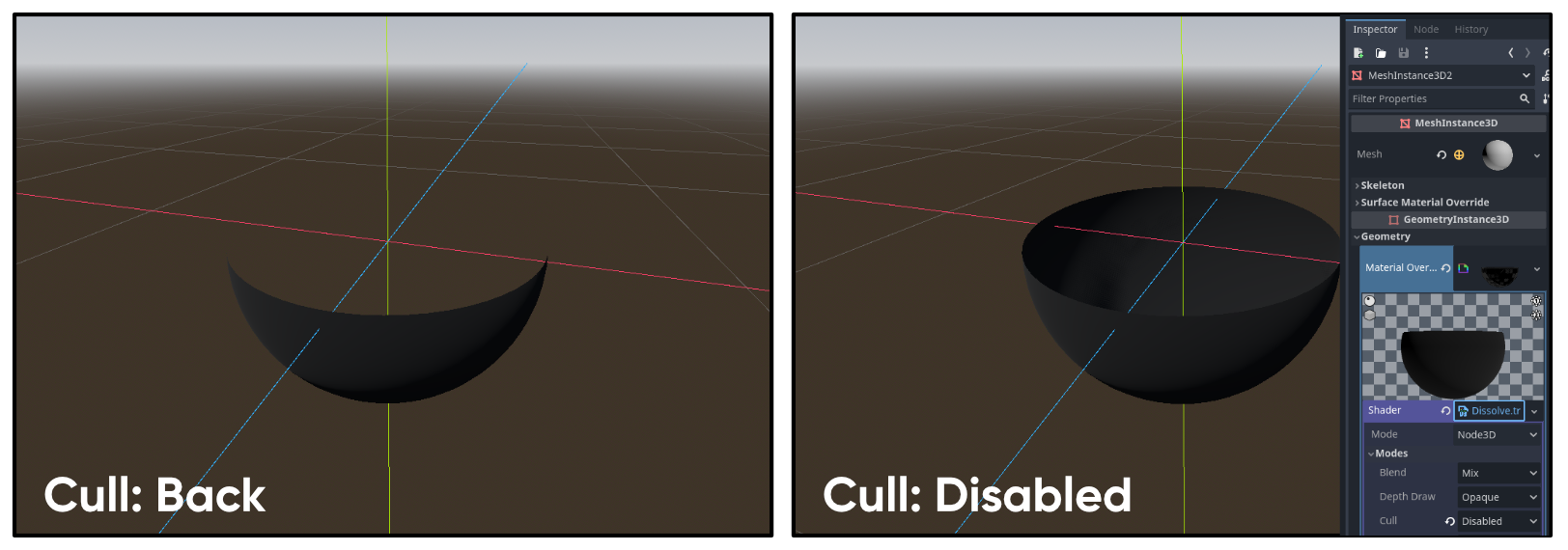
If I look at my test scene, we can see the changes being applied already. Since part of the object has been cut away, it looks really strange because we can’t see the inside by default. To enable two-sided rendering, you need to click on the Shader here in the Inspector, then expand Modes and change Cull to Disabled. You’ll only see the outer shell of the object, but it’s a damn sight better than seeing nothing on the insides.
That’s the easy bit - now, let’s add some noise to change the shape of the edges. This is where I discovered a bit of a double-edged sword with regards to Godot, because there’s no built-in node that just gets you some noise values, which was initially disappointing. But then, I found out you can define your own custom nodes! Whereas in Unity, the best you’ve got is creating a Custom Function node, in Godot, we can do something similar with the VisualShaderNodeCustom class, but I think this is more powerful. Basically, we can write a script that extends the VisualShaderNodeCustom class, give it an @tool attribute (which makes it run within the Editor), and then overload a bunch of functions which define the name of the node and what its behavior, inputs, and outputs are.
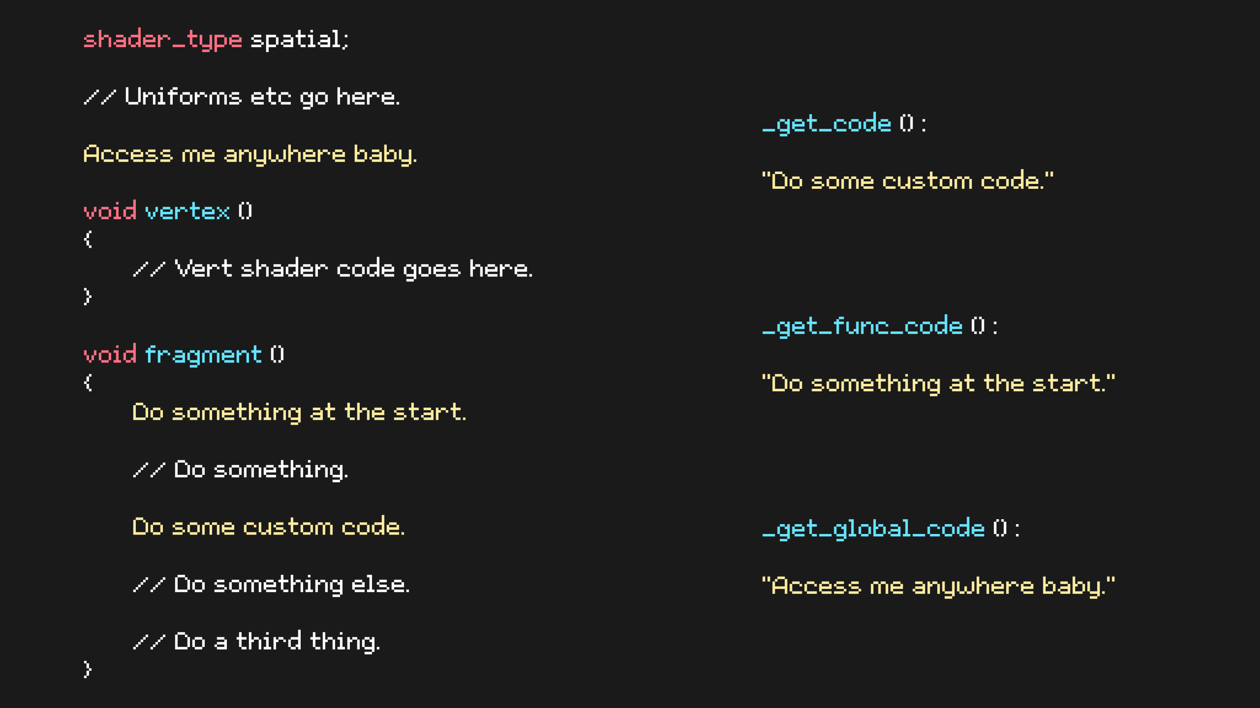
In fact, it can inject totally custom GLSL code into several places:
_get_code()inserts code wherever you place the node. That’s the one you have to define and it’s the one I expected to see._get_func_code()inserts code at the start of the shader stage, so if you add the node anywhere in the fragment stage, this code runs before anything else in the fragment stage._get_global_code()is super useful, as it inserts code at the top of the shader file, so you can use this for helper functions and variables. And I love this! It’s something Unity sort of can’t do without hacks, I think.
And then you can reuse this node in as many graphs as you want through the same node search bar as the built-in nodes. This makes it easy to create your own library of shader nodes that you can slot into any project you want. Luckily for me, there’s a Godot docs page that outlines exactly how to set up a Perlin Noise 3D node. Unity’s built-in noise nodes only operate in 2D so this is fantastic.
I won’t go into detail about how the Perlin Noise code works because that’s a whole article in and of itself - just know that it generates greyscale cloud-looking values using some input value as a seed. This node calls this input UV because the noise is commonly applied like a texture, but you don’t need to use a UV coordinate as input. In fact, we won’t be. This implementation also takes handy Offset, Scale, and Time inputs, but we’re only going to make use of scale. I’ll input a FloatConstant equal to 0 to the Offset and Time values.

For the UV, I’m going to use WorldPos using the VaryingGetter node from earlier. The full vector, not just the y-component. For the scale, I’ll use a new FloatParameter called “Noise Size”. The resulting value from the node is a float between 0 and 1. I want the noise to act as an extra height offset and I want it to be customizable, so I’m going to remap its values. I’ll add another FloatParameter called “Noise Scale”, then use the nodes (two Multiply and one Subtract) in the following screenshot to remap the [0, 1] range to [-Noise Scale, +Noise Scale]. It’s a shame there seems to be no built-in Remap node like in Unity! I can then add the result to the y-component of the height. Use this as the X input to the Step node.

The last thing I want to add is an emissive glow around the edges left after the cutoff. To see the glow, I’m going to head to my main scene which houses all of my shaders, click on the Camera, add a new Environment if it doesn’t have one, and make sure that the Glow option is Enabled.

With that out of the way, let’s return to the graph. I’m going to add one more FloatParameter called “Glow Thickness”, which I’ll give a default value of 0.05, since we want it to be just a thin edge. I will subtract this from the Dissolve Height parameter we previously added. This forms a second cutoff threshold, so I will add a second Step node just below the first one, then pass the new threshold into the Edge slot, and pass the noisy y-component from before to the X slot.

If we used this for the Alpha output, we can see that this shape is almost the inverse of what we had, except there’s a small bit of overlap.

Using this value, I will add a final ColorParameter called “Edge Color”. For its default value, I’ll make it blue, but I will make sure to swap to the RAW tab and elevate the color sliders to values exceeding 1, as this produces a glow. Finally, we can multiply the mask and the Edge Color together - make sure that you use a VectorOp node - and output the result to Emission. The graph is now complete!

Hologram Effect
Next up on the docket is a simple hologram effect, where scanlines scroll down the object and Fresnel light brightens up the outer parts.

The scanlines will be driven by a texture. This texture, to be specific:

On a new VisualShader, I’m going to add a node called Texture2D, which reads texture data and outputs a color. There are different options for reading a texture, so I’m going to pick SamplerPort, which reads whatever texture we slot into the sampler input. For that, I’ll create a Texture2DParameter so that we can swap out the scanline texture with a different one if we want. I’ll name it “Scanline Texture”. I’ll also add a ColorParameter called “Scanline Color” which defines the tint color for just the scanlines - I’ll use a separate color for the Fresnel later. I’ll multiply the texture and color together, then output the color to Emission and just the alpha component to the Alpha graph output. What we have so far isn’t super interesting, because the texture is just mapped to the surface of the object. I want it to scroll downwards over time from top to bottom, so we’ll need to change the UVs we use for the Texture2D node.

I’ll give myself plenty of space to work with to the left of the nodes we just added, then add a FloatParameter and name it “Scanline Scroll Speed”. You can guess what this controls! I will also add a Time node, which I believe gives us the number of seconds since the game started. Let’s multiply them together - now we have a timing mechanism.

Next, we’re going to work on scrolling from top to bottom. I want to do this based on the object’s world space height, but you’ll remember from the dissolve shader that there’s no built-in node for that, so once again let’s go to the Vertex stage, add a Varying called “WorldPos”, and input the model matrix times the vertex object-space position using a TransformVectorMult node, which gets us the world-space position.

Then on the Fragment stage, we can use a VaryingGetter and a VectorDecompose to get the y-component of the WorldPos. Let’s add a FloatParameter called “Scanline Scale” and multiply it with that y-component. This will let us control how closely packed the scanlines are. The last step is to add this value to the timing mechanism we added previously, then create a new Vector2 using the VectorCompose node and slot our value into Y. The X slot can use whatever value we want because my scanline texture is just horizontal lines, so all values of X give the same output value for a given Y. This gives us a new set of UVs we can use for the Texture2D node.

All that’s left to add is the Fresnel light. Luckily, there’s a built-in Fresnel node which works very similarly to Unity’s. We can slot in a Power value to scale the size of the Fresnel effect - the higher the input, the smaller the Fresnel effect. For that, I’ll add a FloatParameter called “Fresnel Power”. Let’s multiply it by a ColorParameter called “Fresnel Color” - remember that we can go to the RAW tab in the color picker to choose high-intensity colors.

Now, setting up the final graph outputs is a simple case of adding the scanline and Fresnel values together and slotting the result into the Emission output, then adding their alpha values together and slotting the result into the Alpha output. This graph is now also complete!

Hull Outlines
I left the simplest graph ‘til last! Inverted hull outlines are a very basic method for adding outlines to objects, where you expand the mesh itself slightly in the vertex shader and color the entire object one color, then render only its back faces. Then, you render the object normally a second time and it’ll render over the expanded, inverted mesh.

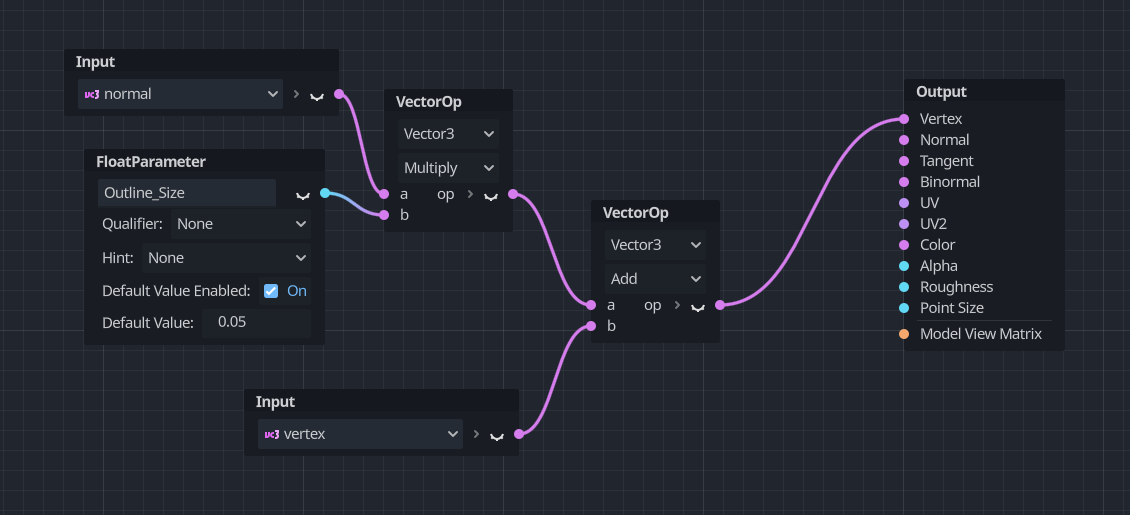
I’ll jump straight over to the Vertex tab of the graph and add a FloatParameter called “Outline Size”. We’ll want it to be a fairly small value like 0.02 or 0.05, somewhere in that ballpark. I’m going to multiply this by the normal vector using a Normal node, which gives us an offset value for moving the position of the vertex, then I’ll add the result to a Vertex node (the object-space vertex position, if you’ll recall), which has the effect of expanding the mesh. This can be slotted into the Vertex output, which is the vertex position.
Over in the Fragment stage of the graph, all I will do is create a ColorParameter called “Base Color” and output it to the Albedo. And that’s it, the graph is complete, although we’re not actually inverting the hull yet, just expanding it, so we’re rendering a slightly bigger sphere.

In the Inspector, I’m actually going to give my sphere a new StandardMaterial, which is essentially the same as Unity’s standard Lit material. This is the normal rendering of the object. If we expand the material by clicking it, one of the options is called “Next Pass” which lets us attach a second material. This is where I’ll add a new ShaderMaterial and use my HullOutline shader. Click on the Shader field and make sure that under Modes, the Cull option is set to Front. That means the front faces will get removed and only the back faces are rendered, thereby inverting the hull like we wanted. And that’s the outline effect completed!

Conclusion
This was my first real attempt at making something in Godot’s VisualShaders. The process is surprisingly similar to using Unity Shader Graph for the most part, but with obvious differences that will take some time to get used to. For one, when you type “Multiply” into the search bar, there are seven different nodes with the exact same name which output different types. In Unity, there’s just one, and it can contextually figure out what output you want given its inputs, plus it can take matrices, but in Godot you need a TransformOp to multiply with other matrices, or TransformVectorMult to multiply with vectors. And then there was the thing with getting world positions.
But it’s not all frustrations! I’m pleasantly surprised by how fast Godot is with things like compiling scripts, and for that matter, GDScript seems alright, although I haven’t used it much so far. I’m definitely gonna need to sit down and work with Godot a bit further but I’m excited to write more articles in the future that focus on Godot, so look out for more Godot effects on here!
Subscribe to my Patreon for perks including early access, your name in the credits of my videos, and bonus access to several premium shader packs!
Acknowledgements
Special thanks to my Patreon backers for Dec 2023 - Feb 2024!
CD Ilello JP Scott Harper Verisutha Jack Dixon Morrie Mr.FoxQC Leonard Pascal pixel_Wing Alexis Lessard claudio croci Hassan Karouni Jun Lukas Schneider Mikel Bulnes Ming Lei Muhammad Azman Olly J Paul Froggatt Will Poillion Zachary Alstadt 源 刘
