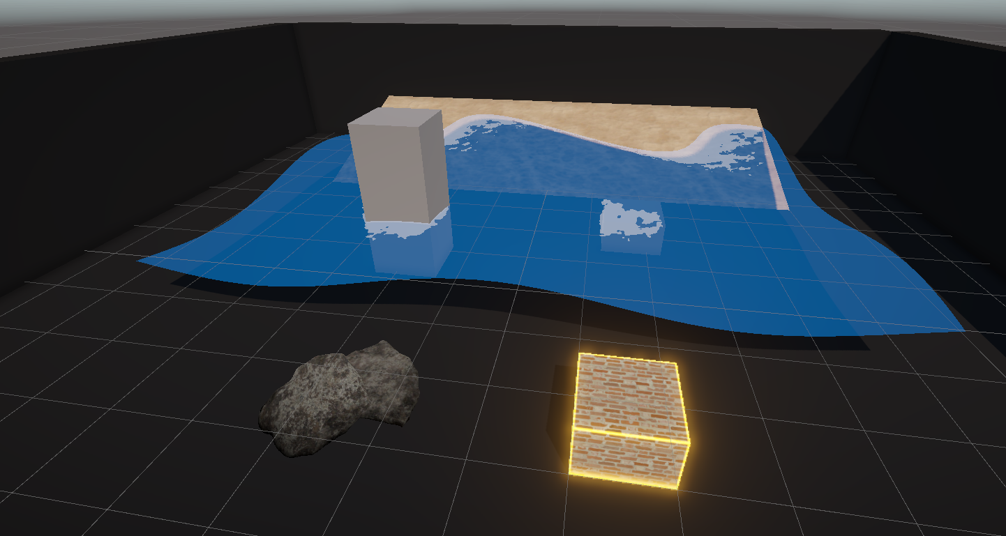
In Part 9, we will continue exploring scene intersection shaders. Last time, we made this basic screen-space ambient occlusion effect, which included making a subgraph for detecting intersections, and in this Part, we’re going to make wave foam and edge glow effects based on the same principles. The graphs in this Part will be a fair bit longer than many of the graphs we’ve seen so far, so I also hope this tutorial will serve as good practice for making more complex effects!
Check out this tutorial over on YouTube too!
Wave Foam Effect
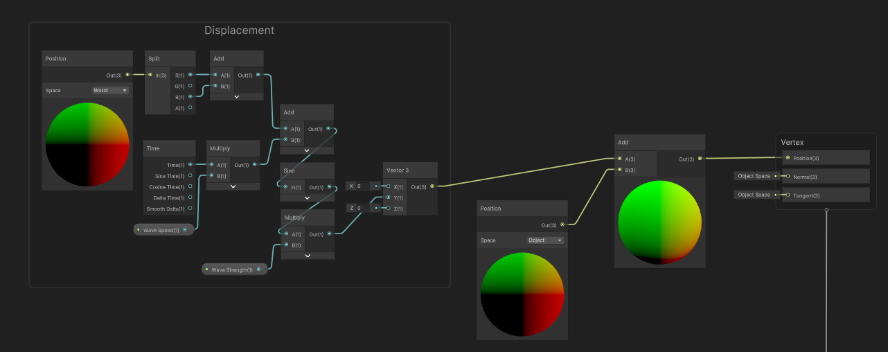
Let’s start with the wave foam effect. I’m going to copy the “Waves” graph that we created in Part 5, and name the copy “IntersectionFoam”. To recap this shader, we modified the position of each vertex over time according to a sine wave and set each pixel to a base color, nothing too fancy.

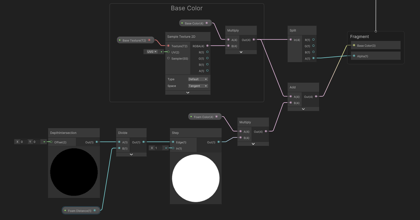
What I want to do is add foam around the parts of the water mesh that intersect with other objects. So of course, we can start off by adding the DepthIntersection subgraph we created in Part 8, which will return the difference between the depth of the pixel being rendered and the depth of the pixel already drawn at this position. This graph may or may not already be using Transparent rendering, but we can go to the Graph Settings and check the Surface type just to confirm.

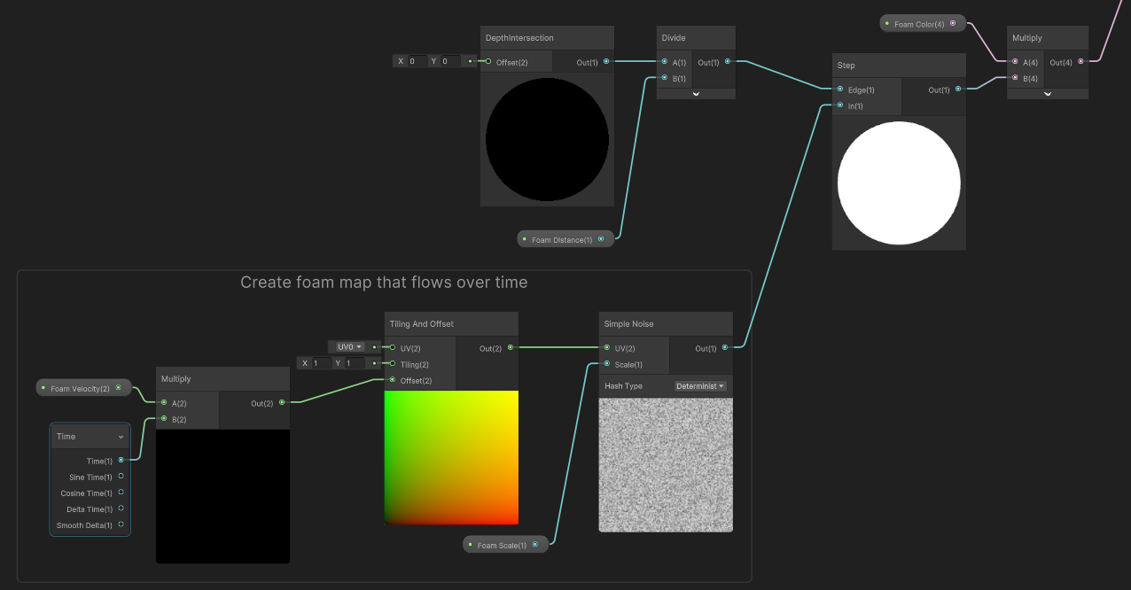
First, I want to introduce some sort of threshold value so that we only apply foam where the depth difference is small. This will work differently to the IntersectionOcclusion shader, where we simply used a power value. Instead, this time I will add a Float property called Foam Distance, and make it a Slider between 0 and 5; this controls how far out the foam can appear from intersected objects, where 0 means there is no foam and 5 means it’ll extend up to 5 meters, although you probably won’t set it that high. Let’s take the DepthIntersection value and divide it by the Foam Distance. That means the output from the Divide node gets larger when the Foam Distance gets smaller.

Next, we’re going to use a Step node, which outputs 0 if In is less than Edge, and 1 otherwise. I’m going to connect the Divide output to the Edge slot and hard-code a value of 1 to the In slot for now. Overall, this collection of nodes will output 1 only if the depth difference is below the Foam Distance, as we’ll see shortly.

I will add a Color property called Foam Color, then we can drag this onto the graph and multiply it with the output of the Step node we just added, then add this to the Base Color values we had at the start of the tutorial and output this to the graph’s Base Color output.
Now, in the Scene View, we can verify that the foam is working the way we intended by changing the Foam Distance. Indeed, when we reduce the Foam Distance to zero, there is no foam, and then the foam slowly extends outwards when we increase it.

Currently, however, the foam appears in these big blocks, which I think we can improve on. At the top of this article, I showed off a sort of splodgy, noisy pattern which scrolls over time, which we’ll add now.
Let’s hop back into Shader Graph and add a node called Simple Noise - I’ll add this to the left of the existing nodes so we have a little space to work with.
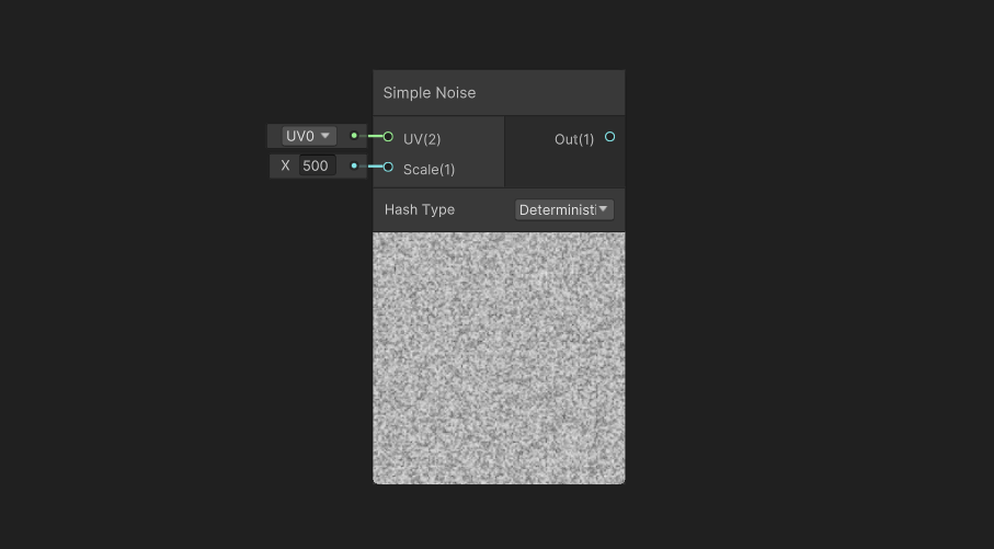
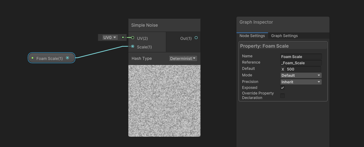
Noise can be very powerful in shaders, as it lets us add natural-looking variation to otherwise unnatural-looking effects. In our case, we’ll use this noise pattern to distort the edges of the foam. You’ll see that the Simple Noise node has two inputs: the UV, which is just a coordinate to apply the noise to - you don’t actually have to use UVs and you could instead use any 2D vector, such as the (X,Y) components of the world position - and the other input is the Scale, which controls the size of the noise. If we decrease this value, then we get “larger” noise clouds overlaid onto the same UV range. We’re going to work backwards to begin with and deal with the inputs to this node.
For the scale, I’m just going to add a Float property called Foam Scale with a default value of 500 and connect it directly into the Scale slot. Easy!
For the UV input, I want to introduce some movement into the effect, because it won’t look terribly interesting if our foam just lies there, stationary. I’ll add a Vector2 property called Foam Velocity, which is going to act as an offset to our UVs. So let’s take the Foam Velocity and multiply it with a Time node’s regular Time value, which counts up the time since the game started, and then feed this into a Tiling And Offset node in the Offset slot. Finally, we can connect the output to the Simple Noise UV slot. This collection of nodes now gives us a noise cloud that scrolls over the surface of the water over time.

The Simple Noise node outputs values between 0 and 1. So, if we connect its output to that Step node we created earlier, and then save our graph and return to the Scene View, we’ll see a massive improvement to the way the foam feels. It’s no longer just a boxy block of color and now it feels as though the motion of the waves is causing the water to foam up around intersected objects!
I’m still a little unhappy with how we have these straight-line edges on the foam, which doesn’t look terribly natural. That’s because we are, ultimately, still performing the intersection check in a straight line from the camera to a pixel on the water surface, so for example, the pixels directly to the left of the box don’t know there’s a giant cuboid in the water. It’s just looking behind itself, seeing a floor, and concluding that since the floor is far away, there is no intersection. Let’s make a couple of changes to address this.

Remember in the last part where we made the subgraph and I said it didn’t need any inputs? Well, that’s true, but it does limit the usefulness of the subgraph because it will only be able to sample the current pixel. If we want to sample nearby pixels instead, then we’ll need to modify the subgraph. Let’s add a Vector2 property and name it Offset, then let’s turn our attention to the Scene Depth node. You’ll see that by default, it has an input already, and this is actually equivalent to a Screen Position node in Default mode.
Unlike the other Screen Position node we added in the last Part, which was in Raw mode, the Default mode does actually get us the (x, y) position of each pixel on the screen, with values between 0 and 1 in both axes. Let’s add the new Screen Position node and our Offset property and connect the result to the Scene Depth node, and now we have the ability to compare the current pixel depth with a nearby pixel’s previously-rendered depth value. Do you see where I’m going with this?
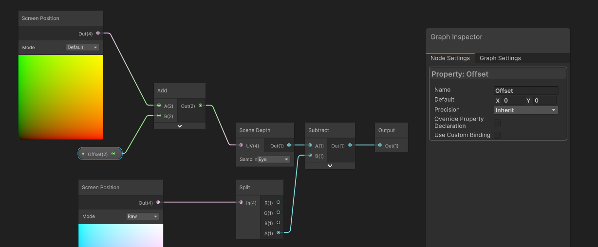
If we save this subgraph, it’s going to update all graphs which use it. Thankfully, if we leave the default value of the Offset property as (0, 0), then it’s not going to change the behavior of any of our main graphs just yet, and they’ll all continue to sample the difference with no offset.
Back on the IntersectionFoam graph, we’ll see those default inputs pop up on the DepthIntersection subgraph node. I’m going to add a new Float property called Depth Sample Offset, which is a Slider that will take values between 0 and 0.1. The reason for the low values is that they represent a proportion of the entire screen width and height, and an offset above 10% of the screen will look pretty bad. Let’s take this property and multiply it with the Simple Noise output. Now, we have an offset value which also distorts over time according to the noise values.
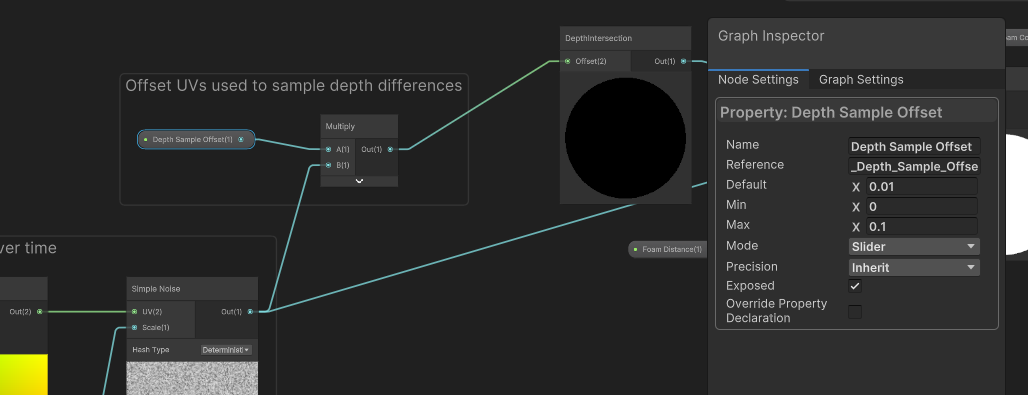
If we slot this into the DepthIntersection node, and then look at our shader in the Scene View, we can increase the Depth Sample Offset to see some foam appear to the side of the intersecting objects. That’s because now we’re comparing the depth of a pixel on the water surface to the previously rendered depth at a different pixel position. So, for example, these pixels can now “see” the cuboid. Since the depth difference is below the threshold defined by the noise pattern, we see foam.
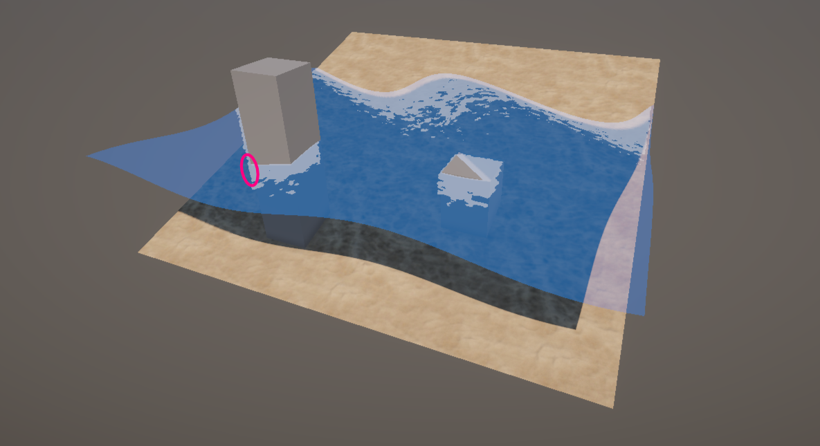
Of course, the problem now is that we see foam all the way along the edge, and that’s because the depth difference for all of these pixels is actually increasingly negative as we go up. We’re using one Step node, and these negative values end up passing the threshold step. So, we’re going to have to make one last change to remove most of these foam parts.
Let’s drag out a new wire from the Divide node and create a new Negate node, which multiplies all its inputs by minus 1. With this node, all those pixels along the edge of the cube now have increasingly positive difference values as you go further up. If we pass the Negate output into a second Step node’s Edge slot, and pass the Simple Noise node into the In node like we did with the first Step node, we’re now performing a second thresholding step which should be detecting everything except the parts of the water straddling the edge of the cube. We can then multiply the result of both Step nodes together and instead connect that to the Foam Color multiplication.
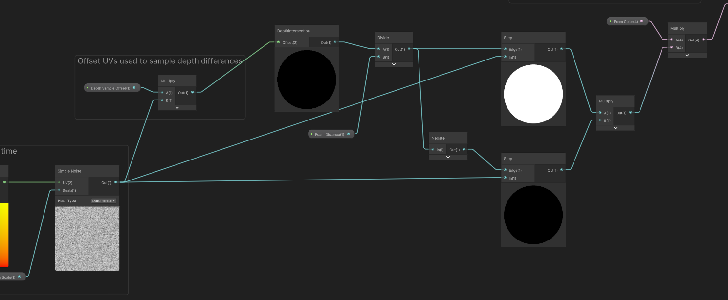
If we hit Save Asset and return to the Scene View once more, then most of those weird-looking foam bits have disappeared. Nice!

Now, if you increase the Depth Sample Offset value too much then the foam will start to look entirely disconnected from the intersecting objects, so you should keep it high enough to see a bit of foam spraying off in one direction, but low enough that the foam still looks connected in the opposite direction.
You’ll also only be able to see foam extending in one direction - so, in this case, there is only extra foam to the left but not to the right - but I decided this looks okay because it looks like the foam is flowing to the left in accordance with the larger waves we created in Part 5, which are also moving to the left.
Subscribe to my Patreon for perks including early access, your name in the credits of my videos, and bonus access to several premium shader packs!
Edge Glow Effect
The second effect I want to cover is an edge glow effect, where the glow snaps to the intersection points when you move it into another object. This sort of effect can be useful when we’re creating something like an energy shield, which I made a longer tutorial about already, but here we’re gonna keep things basic.
To create this effect, I’m going to rely on the object’s UVs. Essentially, any UV value in either axis that’s close to 0 or 1 is going to register as a “glowing” part of the object. Then, we can detect intersections as we have been doing so far and add those parts to the “glowing” region, apply an HDR color to that region, and add the resulting color to the Base Color.
I’ll start by creating a new Unlit shader via Create -> Shader Graph -> URP -> Unlit Shader Graph, and name it “IntersectionGlow”. I’ll start off with Base Color and Base Texture properties wired up like this - and then at the end, we’re going to add the edge glow to this value and output the combination to the graph’s Base Color output.

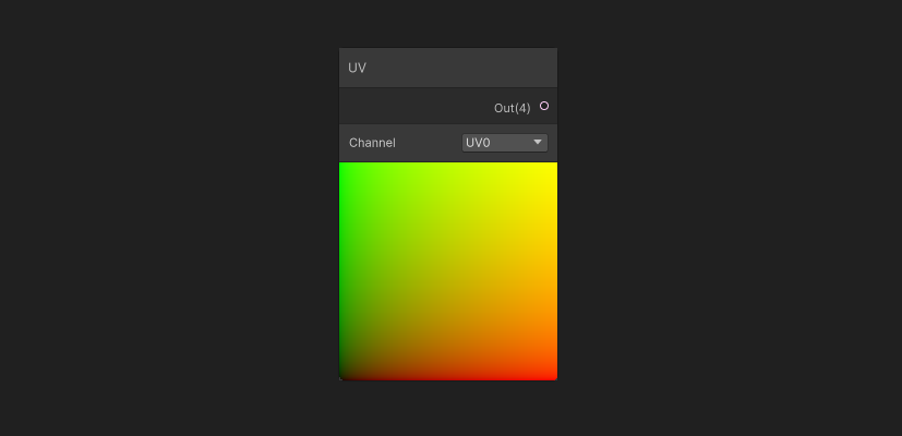
Then, leaving plenty of space to the right, I’m going to add a UV node. To recap UVs, these are coordinates applied to each vertex of your mesh that defines where Unity should read texture data. The default Unity cube has UVs such that each face of the cube shows a texture in its entirety, for example. We’re going to use the UVs to add a glow to the edge of the object, forgetting about intersections for now.
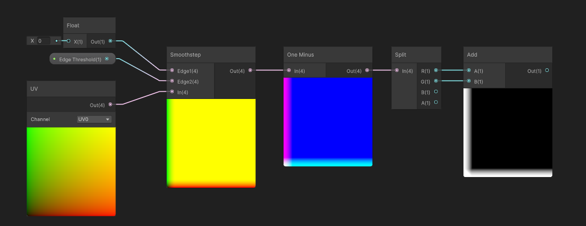
First, we’re going to detect UV coordinates that are close to 0 in either the x- or y-axis (which we can also call the u- and v-axes). For this, I’ll add a new Float property called Edge Threshold, which will be a slider between 0 and 0.5, which is going to define what proportion of the UV space will be covered by the glowing edges. 0 would mean no glow, and 0.5 covers half the length of the object from both sides. I’ll drag out from the UV node to create a new Smoothstep node, passing the UV into the In slot, then connect a new Float node with a hard-coded value of 0 into the Edge1 slot and the Edge Threshold property into the Edge2 slot.
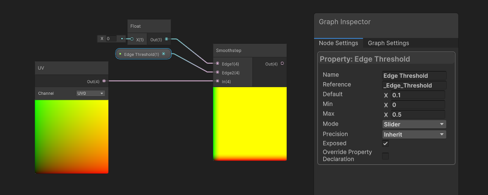
Now, the preview on the Smoothstep node is pretty colorful, so what exactly is happening here? There’s a few things to note.
- The UV node outputs a
Vector4, which you can see by the 4 in brackets next to the output. - In almost all cases, UVs only use the first two components (x and y), but it’s technically possible to attach UVs with three or even four components to each vertex.
- For our purposes, we’re going to ignore that and just assume that only the first two components are in use.
- So far we have thought of the
Smoothstepnode as operating on just oneFloatvalue input and twoFloatthresholds, but what happens if you connect aVector4to the In slot instead of aFloat?- In this case, Unity just runs the
Smoothstepon each component individually. - It’s going to run
Smoothstepon the UV’s x-component and output that in the first component of the output. - Then, it’s going to run
Smoothstepon the UV’s y-component, and so on. - We don’t need to go through the tedious process of splitting the UVs into individual components before passing them into multiple
Smoothstepnodes.
- In this case, Unity just runs the
- Since the
Smoothstepis outputting values in multiple channels, it’s choosing to display them combined as an RGB color. That’s why we see red, green, and yellow in the node preview.
You can kind of see from the preview that we’re detecting edges along the bottom and left-hand edges of the UV space. Although at the moment, the Smoothstep is outputting 1 when the UVs are above the Edge Threshold, so I’ll use a One Minus node to reverse that. For the next step, I do only care about the x- and y-components, so I’m going to use a Split node and then add the x- and y-components together, giving us a final ‘edge glow’ amount for these two sides of the UVs. Now we can deal with the upper and right-hand edges.
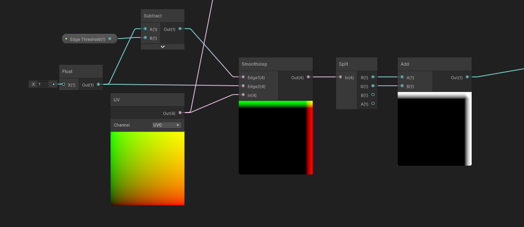
The upper-right edges are the two edges where the UV values are close to 1. Let’s drag a second Smoothstep node out from the UV node, and this time, we want a Float value of 1 in the Edge2 slot and 1 minus the Edge Threshold in the Edge1 slot. This time we don’t need to do a One Minus after the Smoothstep because all input values below (1 minus Edge Threshold) will have 0 as an output, so we’ll just use a Split node to get the x- and y-components and add them together. Now we have an ‘edge glow’ amount for the top and right-hand edges.
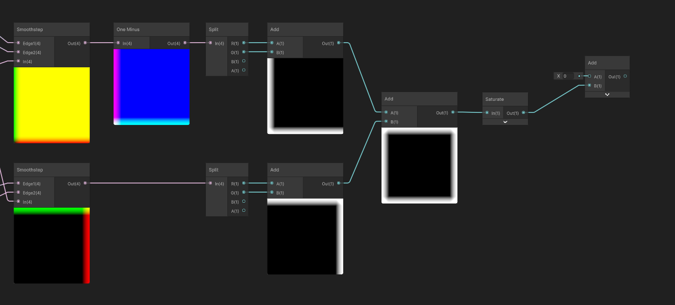
We can add the bottom-left and top-right values together, then Saturate the result, because as it stands, these two corners would have a few pixels that sum to higher than 1, and now that’s the final glow amount from the UVs. Before we deal with the intersections, I want to see what this looks like in the Scene View, so I’m gonna pass this into an Add node - later, this is where I’m going to add the intersections - and now we can deal with coloring these edges.
I’ll add a new Color property called Glow Color and make sure it’s an HDR color so that we can increase its intensity in the color picker and actually make it glow, then Multiply the Glow Color with the Add node. Then, we can add this with the Base Color nodes from the start of the shader, output the result to the graph’s Base Color output block, hit the Save Asset button as always - if you’re like me, you still forget to do this sometimes - and then let’s head to the Scene View.
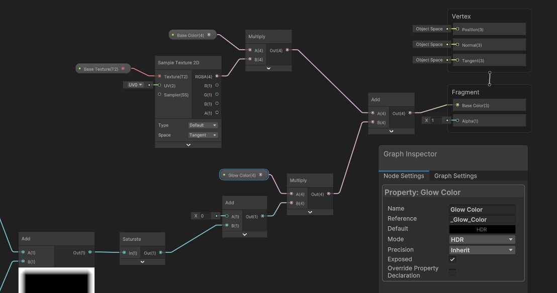
The glowing edges are working well (provided your scene has a Bloom post-processing effect, which I covered in Part 6), but of course, we haven’t added intersections yet so if this were really being used as an energy shield, it’s going to look weird if it clipped through the ground. Probably wouldn’t use a brick texture either, but that’s neither here nor there.
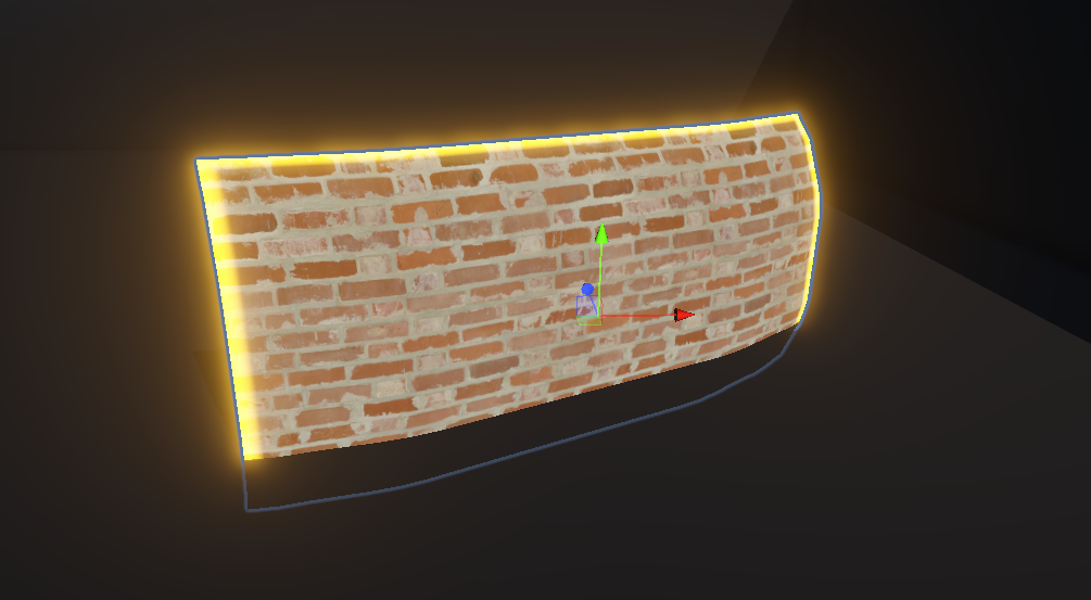
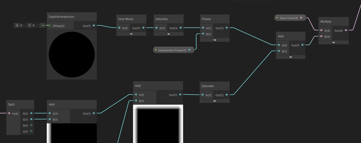
Let’s head back into Shader Graph and incorporate those intersections. I’m going to do this the same way I did the intersections in Part 8, by using a Float property called Intersection Power. This one can also be a Slider between 0.01 and 25. We’ll use the same nodes as last time:
- Let’s add a
DepthIntersectionsubgraph node to get the intersection values to start off. - We’ll feed that into a
One Minusnode so that pixels at the intersection point use a value of 1 and it gets lower as you get further from an intersection. - Next, we need a
Saturatenode to force negative intersection values (which would break everything) to snap to zero. - Then, we can pass that into a
Powernode with theIntersection Powerproperty in the B slot. - Finally, we can output this intersection detection value directly into the
Addnode we created earlier, and that’s the graph complete.
We can hit Save Asset, return to the Scene View, and now we’ll see glowing edges around the intersection points too. Just make sure you tune the Intersection Power and Edge Threshold property values so that both types of glow look about the same in terms of thickness.
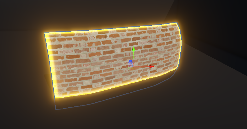
The main limitation of this shader is that you need to set up your vertex UVs in such a way that all the edges of the mesh are near 0 or 1 in UV space. For instance, a sphere mesh wouldn’t work very well with this shader because of the way its UVs are set up, but it does work for this shield mesh because I manually made sure the UVs line up with the edges.

That said, if all you’re interested in is the intersection edge and not the UV-based glow, you can remove a great deal of the graph and still have an effect that works well with sphere meshes.
Now, what was the point in creating this shader in particular? Well, I wanted to show you that some shader effects require us to take two concepts - in this case, UVs, which you’ve been seeing since Part 2, and intersections - and sort of add them together to make something greater than the sum of its parts. And I think that’s an important lesson to learn, because the more complex effects you create might require you to think outside the box about how completely distinct kinds of nodes can be used to create similar things - like here, where UVs and depth intersections are both being used to create glowing edges, but in two very different ways.
This was the longest Part yet! I hope you learned a lot about a variety of nodes and maybe this might inspire you to go back through the previous parts and have a think about how to combine some of the things you learned together to create something more complex and interesting. Until next time, have fun making shaders!
Subscribe to my Patreon for perks including early access, your name in the credits of my videos, and bonus access to several premium shader packs!
Acknowledgements
Special thanks to my Patreon backers for May 2024!
Leonard Michael Verisutha Webmaster Johancity Jack Dixon Morrie Mr.FoxQC Adam Meyer Alexis Lessard claudio croci Jun Lukas Schneider Muhammad Azman Olly J Paul Froggatt Will Poillion Zachary Alstadt 源 刘
