In Part 7 of this series, we’re going to talk a little more about lighting. We talked about ambient, diffuse, and specular lighting in the previous part, but we can go beyond those basic lighting types!
Check out this tutorial over on YouTube too!
Fresnel Lighting
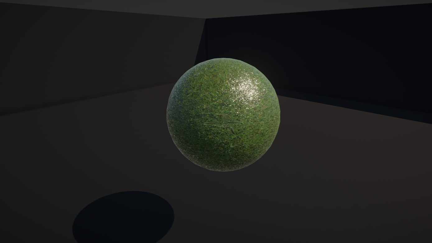
One kind of lighting I’m a big fan of is called Fresnel, named after a guy called Augustin-Jean Fresnel who did a whole bunch of optics-related stuff, including inventing the Fresnel lens. Obviously. Put simply, the Fresnel effect is the principle by which objects become more reflective when you view them at really shallow viewing angles. Unity’s Lit Shader Graph does implement this already, and it’ll manifest on a sphere mesh as a highlight around the edges. It’s actually a type of specular reflection so it’s impacted by the smoothness of the material - higher smoothness means more Fresnel reflections. In this screenshot, the left hand side of the sphere (which is ostensibly in darkness) still has a thin strip of lighting at the extreme edges.
However, for a moment, let’s separate the idea of the Fresnel effect in the physical world from the general idea of reflections that get stronger when viewed at shallower angles. If you want to add Fresnel light to your object with zero regard for real-world physical accuracy, we can do that with Unity’s built-in Fresnel Effect node.

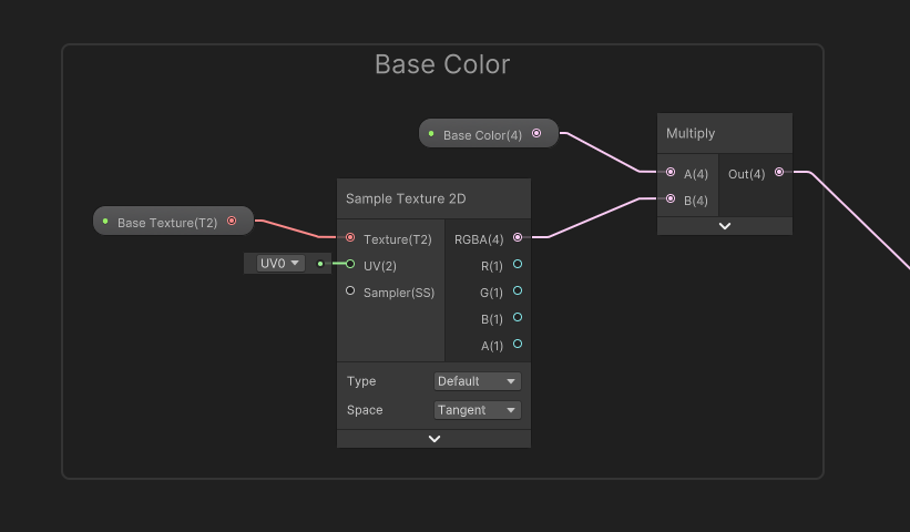
You can use this even within an Unlit graph, which is what I’m going to do - let’s right-click in the Project View and go to Create -> Shader Graph -> URP -> Unlit Shader Graph to create a new Unlit graph, which I’m going to name “FresnelHighlight”. I started by quickly wiring up a Base Color and Base Texture like you’ve seen a couple of times now.
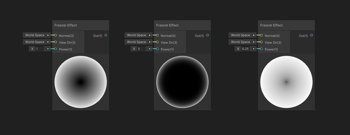
If we go ahead and add a Fresnel Effect node to the graph, we’ll see three inputs: a normal vector and a view vector, which in most cases we can just leave alone, plus a Power value. If we increase the power, the ‘edges’ as it were of the Fresnel get thinner, and vice versa. You probably shouldn’t go below 0 but it won’t actually break anything. The output is a floating-point number between 0 and 1.
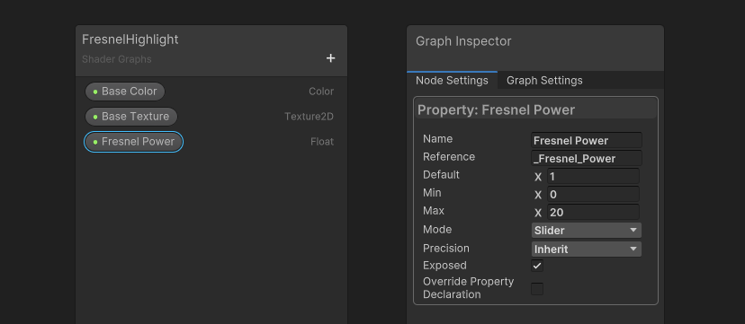
I’m going to use this node to add a highlight effect to my object. For that, I’ll add two properties to the graph: one is going to be a Float property named Fresnel Power. If I click on it and go to the Node Settings, I’ll also change the Mode to Slider, leave the minimum value as 0, and set the maximum to something like 20. I will also change the default to 1 rather than 0 so that the Fresnel light doesn’t cover the entire surface of the object by default.
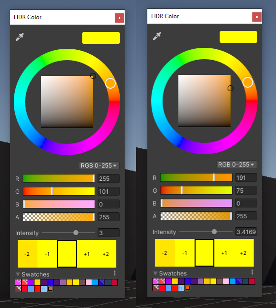
The second will be a Color property named Fresnel Color. This time, in the Node Settings, I will change the Mode to HDR. We’ve used HDR colors before in previous parts of this tutorial series, but to elaborate a bit further, it stands for “High Dynamic Range” which in this context means we can force colors to use values beyond the normal range (which in shaders is 0 to 1 for each color channel value). We do that through the use of an extra Intensity option. What this actually does under the hood is multiply each of the red, green, and blue color channels by 2 to the power of the Intensity value, so if the Intensity is zero, we multiply by 2 to the power of 0, which is 1, which is the same as a regular, non-HDR color.

You might also notice that closing and reopening an HDR color picker might change the RGB and Intensity values because now there are multiple combinations of these values that resolve to the same color - it’s not a bug, I promise! The screenshot below shows two versions of the same color - you can do the math yourself to verify!
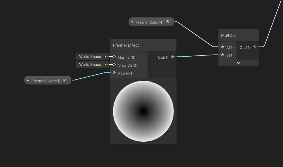
Anyway, we can drag the Fresnel Power onto the graph and slot it into the Fresnel Effect node’s Power input, then we can take the output from the Fresnel Effect node and Multiply it with the Fresnel Color property, effectively giving us an HDR-enabled Fresnel amount. If we choose to use a high-intensity color, then this amounts to a bright glow that will appear around the object.
We can simply add this to the existing Base Color nodes and output the result to the Base Color output to complete our graph. Remember to hit Save Asset so that your changes get saved.

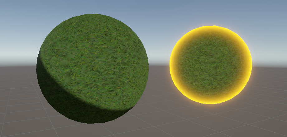
In the Scene View, we can apply the shader to a sphere mesh and the Fresnel acts like a highlight, as intended. This is a really cheap way to bring attention to objects, and you might have seen this approach in games before! However, it only really works properly on spherical and curved objects - objects with flat faces, like cubes, don’t really get a ‘highlight’ effect from this shader.

Subscribe to my Patreon for perks including early access, your name in the credits of my videos, and bonus access to several premium shader packs!
Cel Shading
We’ve just dipped our toes into the idea that we can use lighting for non-realistic purposes, so let’s dive even further into that concept. With a Lit shader, we can supply the physical properties of the object, but what Unity chooses to do with that data is a black box - it’ll just spit out some lighting and we have no control over what it’s doing, at least not in Shader Graph. That gives us limited ability to create non-photorealistic objects, often abbreviated as NPR for non-photorealistic rendering. Not to be confused with National Public Radio, of course.
What we could do instead is use an Unlit shader and calculate the lighting ourselves. This is obviously more involved than just using a Lit shader, but we have total control over the resultant light. I’m going to create a very basic cel-shaded effect. With cel shading, light does not fall off smoothly across the object; instead, there is a hard cutoff between lit and unlit areas of the object. That means we have to do the lighting calculation ourselves and implement a threshold.
I’ll create a new Unlit graph via Create -> Shader Graph -> URP -> Unlit Shader Graph, like before, and name it “CelShaded”. I will once again start with Base Color and Base Texture properties wired up like this:

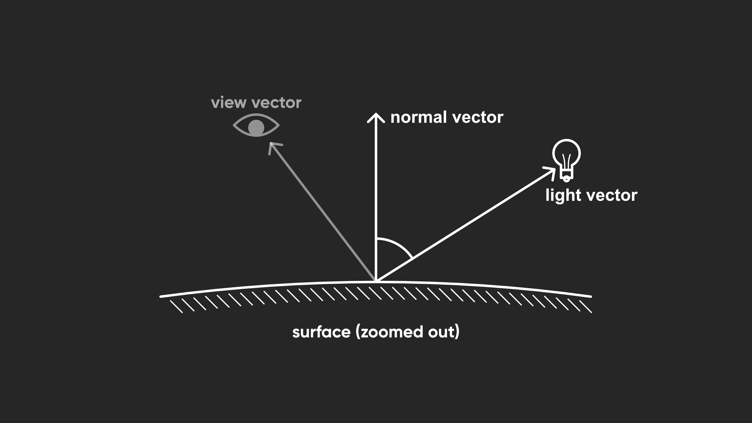
Next, let’s recap from Part 6 how diffuse light works. It’s inversely proportional to the size of the angle between the normal vector, which faces outwards perpendicular to the surface of the object, and the light vector, which faces in the direction of the light. For a directional light, you already have a direction. For a point light, the vector is between the surface and the point light’s position in the world. However, in my shader, I’m only going to account for the singular main directional light in the scene, as it’s usually the one light that contributes the most to objects. We can model this relationship using the vector dot product - the amount of diffuse light is simply n dot l, as the dot product decreases as the angle gets larger, which is what we want.
On the graph, we can get information from the scene’s main directional light by using the Main Light Direction node. This is a relatively new node, and it’s one that I’m extremely happy to see implemented in Shader Graph by default! This currently points from the light origin to the surface so we’ll have to Negate it so that it instead points from the surface to the light origin, then we can take the Dot product of that Negate node and a Normal Vector node. This collection of nodes is doing the basic diffuse lighting calculation.

Next, we’ll deal with the thresholding stage which is crucial to the cel-shaded look. There’s two ways we could do this.
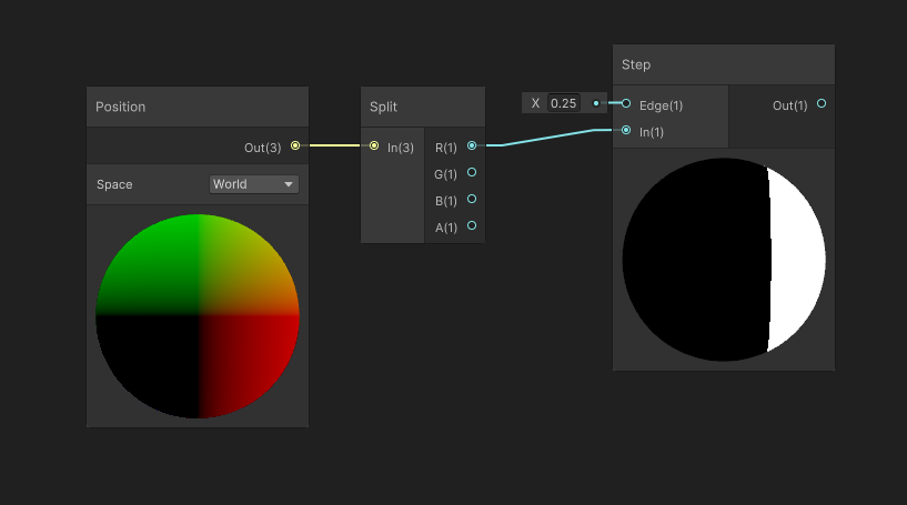
The first involves the Step node. This node takes two inputs called In and Edge. Essentially, if your In input is below the Edge input, then the node outputs 0, or black. Otherwise, it outputs 1, or white. It’s named as such because in math, this is known as a step function. Simple!
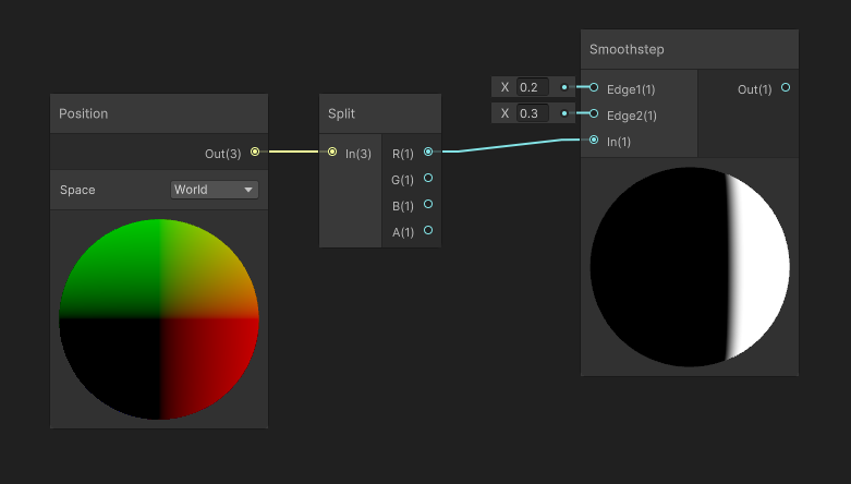
The other way instead uses a node called Smoothstep. It does just exactly it sounds like it does: whereas the Step node introduces a hard cutoff where the output suddenly changes from 0 to 1, Smoothstep has a sort of ‘buffer zone’ where the output values smoothly transition from 0 to 1. So with Smoothstep, you provide two Edge values. If In is below Edge1, the output is 0. If In is above Edge2, the output is 1. And if In is between Edge1 and Edge2, then the output will be something between 0 and 1. This node is great if you want to avoid the razor-sharp cutoff you get with Step. In my graph, I’m gonna go with Smoothstep.
Since it takes two threshold inputs, I’m going to add a Vector2 property to my graph called Cutoff Thresholds. The first component will be used for Edge1, and the second will be used for Edge2. We can go ahead and set that up on the graph using a Split node to separate out the two components of the Cutoff Thresholds vector.
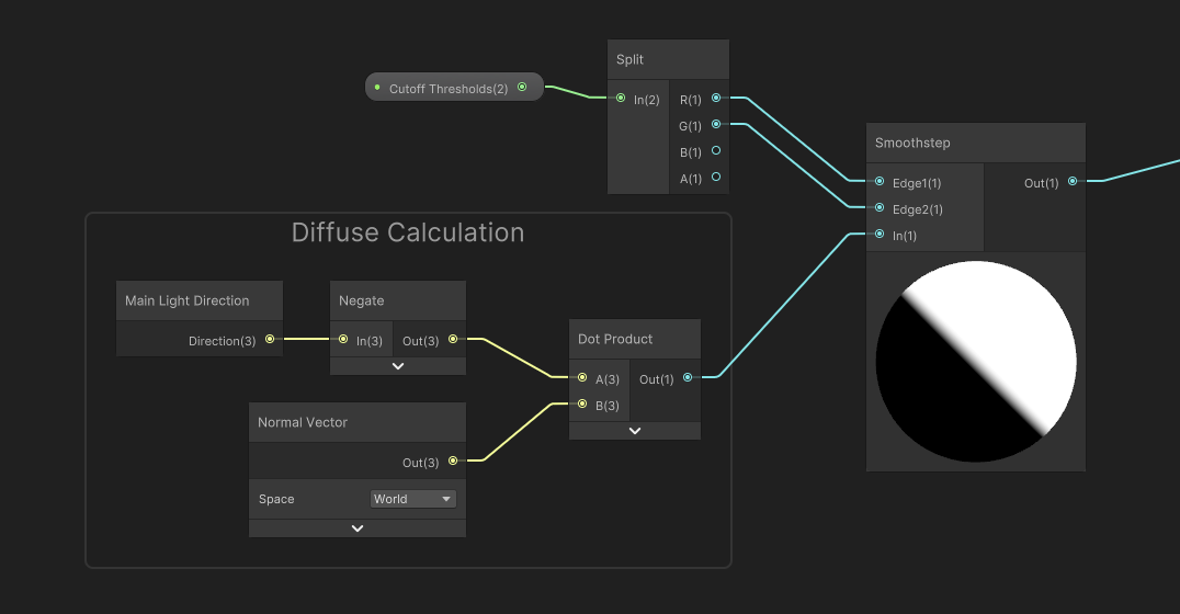
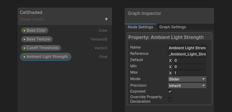
Currently, the values output by the Smoothstep range from 0 to 1. To use this as a lighting value, usually you just multiply it with the Base Color or whatever you’re applying the light to. However, we’re going to get some very dark areas on the object if we do that (i.e., the unlit side of the object will appear completely black, which is probably not quite what you want), so I’m going to control the lower threshold with a new Float property called Ambient Light Strength, which I will make into a slider between 0 and 1.
I want to remap the [0 to 1] range to instead be [Ambient Light Strength to 1], and since we’re starting off with a 0 to 1 range, the easiest way to do that is with a Lerp node. Let’s put the Smoothstep output into the T slot, then the Ambient Light Strength into the A slot, and hard-code 1 into the B slot.
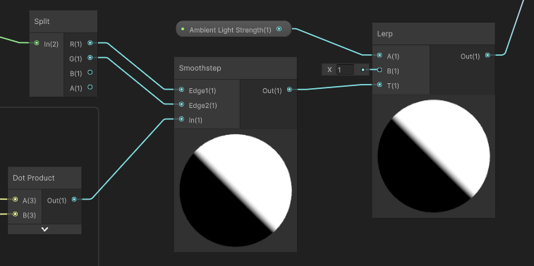
This gives us a final light value, then we can multiply it with the base color and texture values we started with and output to Base Color, and that’s the graph complete, so let’s hit Save Asset.
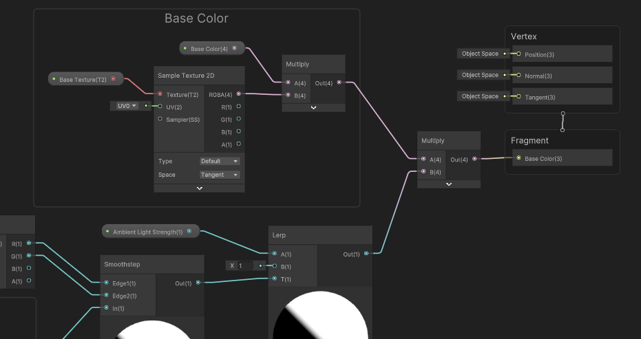
In the Scene View, we can apply the material to our object and we’ll see that the light does not smoothly fall off as it curves round the surface, like before, but instead has a hard cutoff. Here, I’m using Cutoff Threshold values of -0.02 and 0.02, so we get the cutoff halfway around the object, with a very small amount of blending to help soften the edge a little bit.

You can also just set these values to be equal, and you will still get a hard cutoff if you want.

We’ve only implemented diffuse light so there’s no specular highlight either - so there’s a challenge for you if you want to have a go at adding the specular highlights using what you’ve learned in this and the previous part. Until next time, have fun making shaders!
Subscribe to my Patreon for perks including early access, your name in the credits of my videos, and bonus access to several premium shader packs!
Acknowledgements
Special thanks to my Patreon backers for May 2024!
Leonard Rhys Veale-Chan Verisutha Jack Dixon Morrie Mr.FoxQC Adam Meyer Alexis Lessard claudio croci Jun Lukas Schneider Muhammad Azman Olly J Paul Froggatt Will Poillion Zachary Alstadt 源 刘
