Terastallizing is the core mechanic of Pokémon Scarlet and Violet. Despite the uh, graphical challenges this game faced at launch, the Terastallize effect is one part of the game I think looks rather pretty, so in this tutorial, I’m gonna recreate part of it in Shader Graph. Specifically, just the crystallized coating that gets applied to the Pokémon mesh.

Check out this tutorial over on YouTube too!
Analyzing the effect
Let’s have a quick look at the effect in-game. Note that I have no idea exactly how Game Freak implemented this effect themselves under the hood and I’m gonna base my recreation entirely on what I can see, so it won’t be a 1:1 copy.

First, the base Pokémon mesh is still visible beneath the Terastal layer. Second, I can see lots of emissive light bleeding around the edge, which we can cover with a Fresnel effect node. And finally, there appears to be this sort of ‘triangulation’ effect, and light reflects off the triangles differently to how it reflects off the base mesh. That gives me plenty to work with!
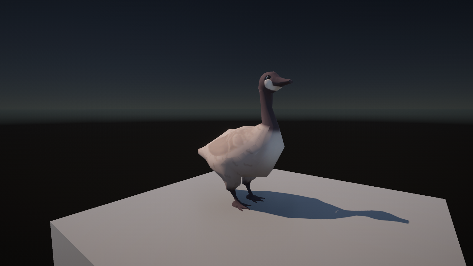
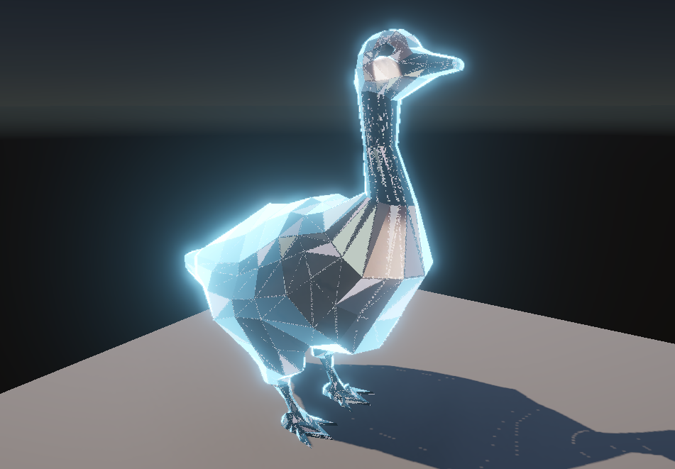
Obviously, I originally chose my best boi Mimikyu to test my effect on but even better: I’ll use this goose mesh, because there’s still no goddamn goose Pokémon and this is the closest I’ll get until Gen 10 ends up being based on Canada.
Creating the shader
Let’s create a new Lit graph by right-clicking in the Project View and choosing Create -> Shader Graph -> URP -> Lit Shader Graph, and name it “Terastallize” or something similar.
The Base Color
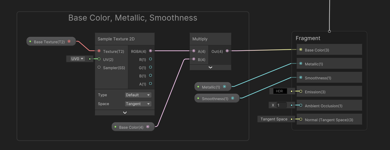
I’ll open up the graph and I’ll start by adding a few basic properties. First, I’ll add a Texture2D property called Base Texture and a Color property called Base Color, then wire up the Base Texture to a Sample Texture 2D node, multiply it by the Base Color property, and connect the result to the graph’s Base Color output. You’ll see something like this on almost every graph I make! I will also add two Float properties called Metallic and Smoothness, and connect them to the corresponding Metallic and Smoothness graph outputs. That’s pretty much it for the base Pokémon mesh.
Fresnel Lighting
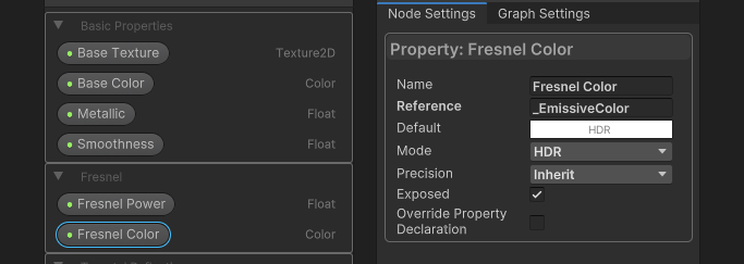
Next, let’s deal with the Fresnel effect. For this I’ll add two properties: one is a Float called Fresnel Power, and the other is a Color called Fresnel Color. For the latter, make sure you go into the Node Settings window and change the Mode to HDR because I want it to use fancy high-intensity colors. Setting an intensity above 0 will make the object glow.
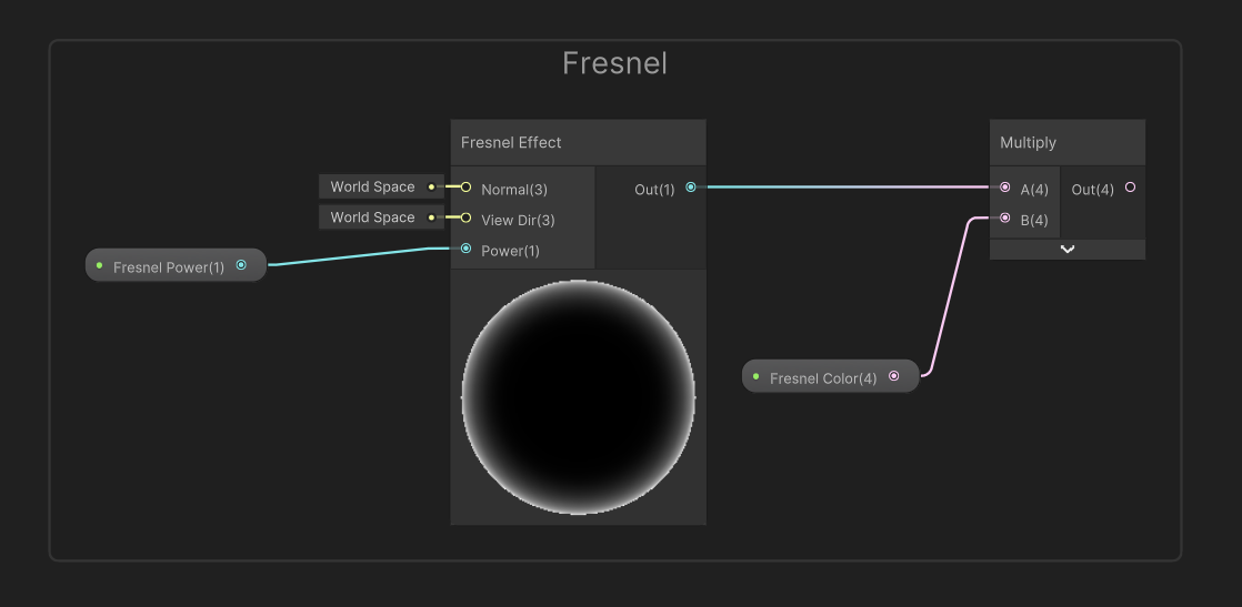
On the graph, all I need to do is add a Fresnel Effect node, a very handy node which comes with Shader Graph, and connect the Fresnel Power property to its Power input. Essentially, the higher the power, the less thick the glow on the edge of the object becomes. I’ll multiply the result by the Fresnel Color property and that’s all we need to do for now. This will eventually be used for the graph’s Emission output, but we’ll deal with that later.
Triangulation
Now we get to the highly reflective ‘triangulation’ effect which I mentioned at the start. The first step in achieving this involves making sure the mesh uses flat faces.
Flattening the faces
Here’s the difference between smoothed and flat-faced meshes:
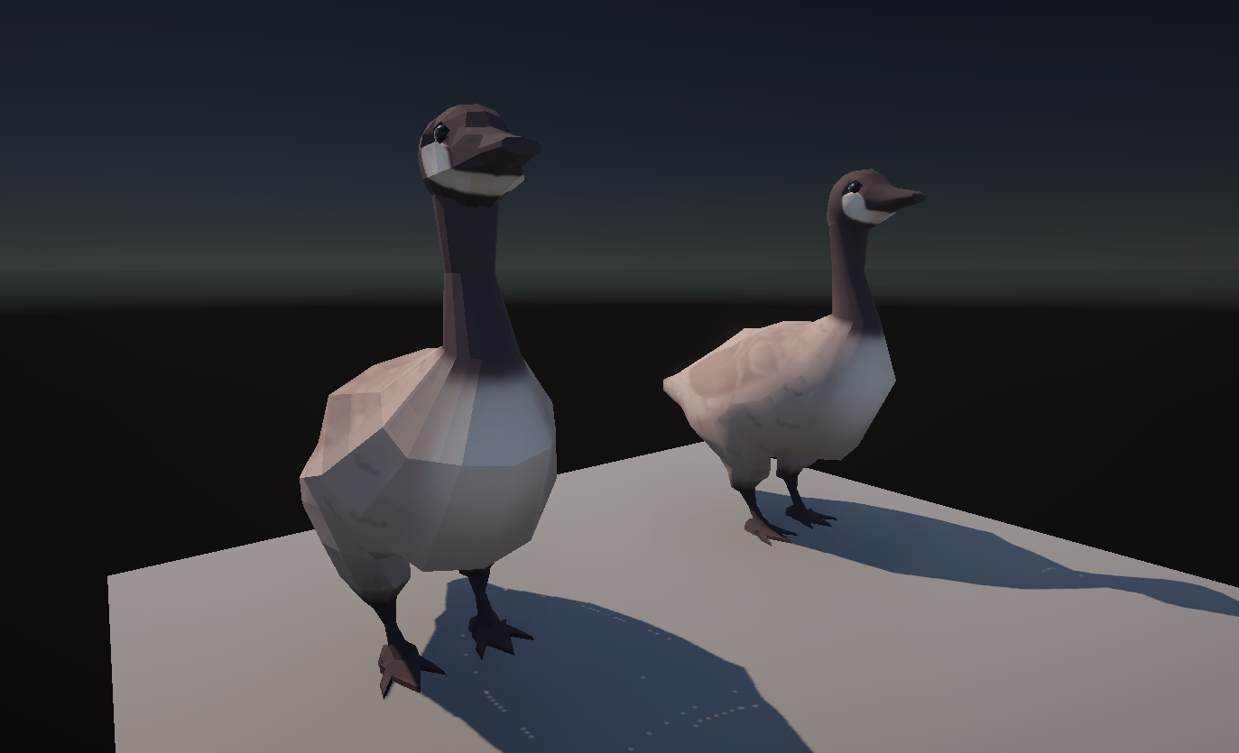
A tedious solution would involve going into every mesh and disabling the smoothing, but we can deal with this in the shader directly. Since normal smoothing doesn’t actually change the world-space position of any given fragment, only its normal vector, which is used for the lighting, we can recalculate the normals manually from those positions. We can do that by taking a Position node, which should be set to world space, and then output it to DDY and DDX nodes.
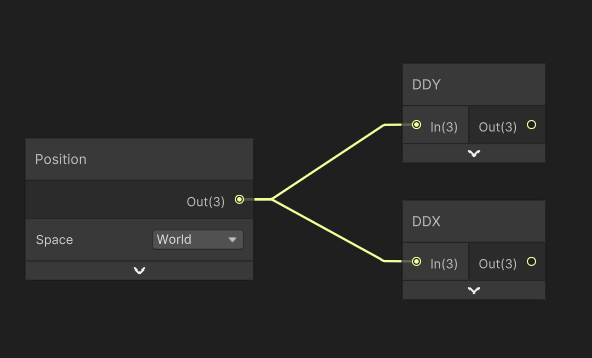
These are called partial derivative functions, but they’re not as scary as they sound. Your GPU typically processes multiple pixels at once, in blocks of 2x2, processing shader instructions basically in lockstep. DDX gets you the difference between the current pixel and the adjacent pixel to the left or right within that 2x2 block of whatever you input into the node. So, if I input the world position, I’ll get a tiny vector that points along the surface of the face.

The DDY node does a similar thing, but with the pixel above or below the current one. And that gets us a second tiny vector that points along the face, but perpendicular to the first one.
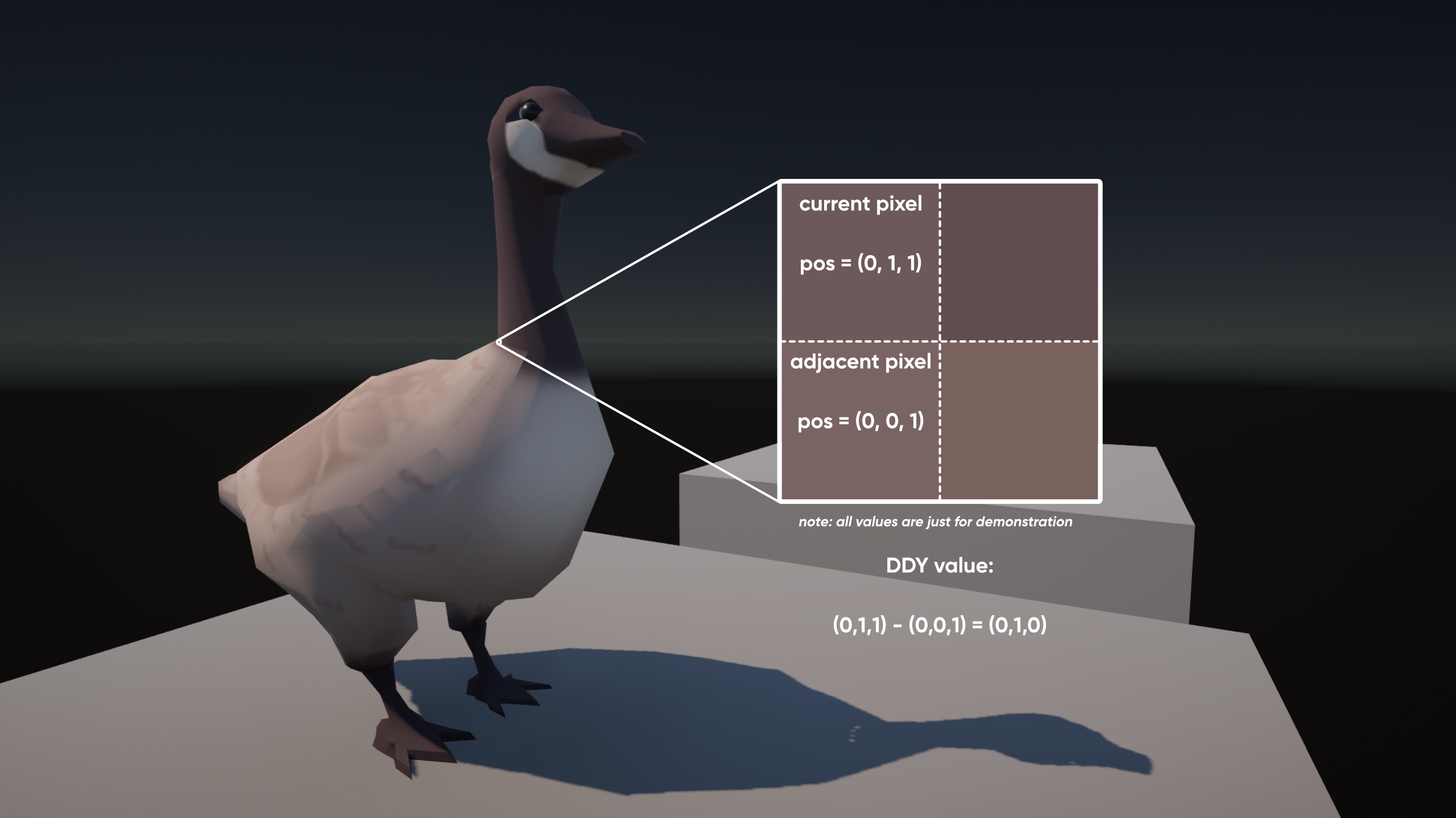
And if you paid attention in your geometry classes, you’ll know that you can take the cross product of the two, and it’ll give us a third vector as output which is perpendicular to the surface of the face - in other words, it’s the normal vector! The key thing is, because the physical face surface is flat, every point on the face will end up with the same normal vector when using this method. Just make sure you get the order of the DDY and DDX right - DDY should be the first input to the Cross Product node. Then let’s Normalize the result and output it to the graph’s Normal graph output.

Now, this shader will turn a smooth-shaded object into a flat-shaded one, so we don’t have to faff around with the mesh import settings and we don’t interfere with the behavior of other shaders which might work best on smooth-shaded objects. That’s helpful for us because our smooth-shaded mesh can use a regular Lit shader for normal rendering, then we can just plop a Terastallize material onto it and the faces will automatically flatten out.
Light Reflections
Now let’s deal with the light reflections on those triangles. There are lots of ways we could go about creating this, and I’m gonna talk about two approaches.
The first is something we unfortunately can’t do in Shader Graph, but I think it’s interesting so I’m gonna talk about it anyway. See, in code-based shaders, the fragment shader can access something called the “primitive ID” through a semantic called SV_PrimitiveID, which is a fancy way of saying we can access a unique ID for each triangle.
float4 frag (v2f i, uint primitiveID : SV_PrimitiveID) : SV_Target
{
     return rand(primitiveID, 0.0f, 1.0f);
}
I could then use those IDs as a seed value for a random number generator and assign a random color or vector to each triangle, something like this:
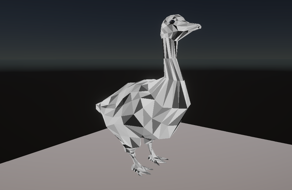
Shader Graph has nodes like Vertex ID, which is similar but obviously for vertices, and Instance ID, which is a unique identifier for each mesh when you’re using instancing, but for some reason there’s no Primitive ID or Triangle ID node. Consider this my official plea for the Shader Graph team to add a Primitive ID node asap because it would be so helpful for effects like these!
Instead, we’re going to create a texture which effectively maps a random value to each triangle. You can do this manually by just exporting the UV layout from whatever modelling software you use, and then painting the texture, but I built a little plugin to automatically do this for me. You can keep using MS Paint if you want. Or if Windows lets you, this is a real screenshot from the Microsoft Store:

Anyway, all my plugin does is read the mesh UV data from the first UV slot and fill in a random color into each triangle, but I won’t go over all the code here. It’ll be included in the GitHub repository for this project. This is also where I found out the Mimikyu mesh I was using has UVs entirely outside the 0-1 range which is just unhinged and caused me a bit of a headache when writing the plugin.
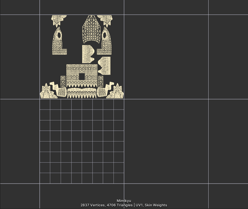
Oh well. I just clicky da button and get my texture, which looks like this if I just apply it to the mesh:
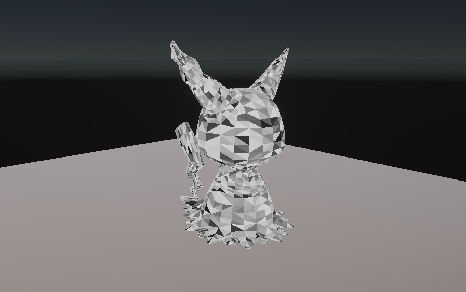
One issue with the texture approach is that you have to bump the resolution quite high to avoid pixelation artefacts, and I also found that I had to turn off mipmaps, change from bilinear to point filtering, and turn off compression, because if any of those things were on then the edges of the triangles suffered from a ton of artifacts. Maybe it doesn’t need to be a ridiculous 8192x8192 resolution like this, but you get my point. Only at this point while writing did I realize how annoying this might be for people who download the entire project from GitHub. Sorry.
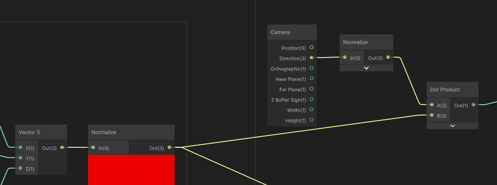
Now let’s return to the graph. I’ll start by adding a Texture2D property called Terastal Triangles, which is gonna be the texture generated by the plugin I just showed you. Let’s drag it onto the graph and sample it. Now, what I want to do is generate a random vector for each triangle. By using the color as a seed value, every pixel on the same triangle will get the same vector. I’m then gonna take the dot product between this random vector and the camera’s forward vector, which gives us a reflection value that’ll trigger on and off random triangles as we swivel the camera around the mesh. Cool, right?
Shader Graph doesn’t have any nodes that give us a random vector so instead I’m gonna pass the red channel of our texture (remember, it’s greyscale so we can use any of the R, G, or B channels) into three Random Range nodes, two of them with additional offsets of 3.14 and 96.07 respectively. Yes, I did pluck those values out of thin air, thanks for noticing. Each Random Range node needs to go from -1 to 1. I’ll construct a new Vector 3 using those values and Normalize the result, and there we have it, a random vector, unique to each triangle.
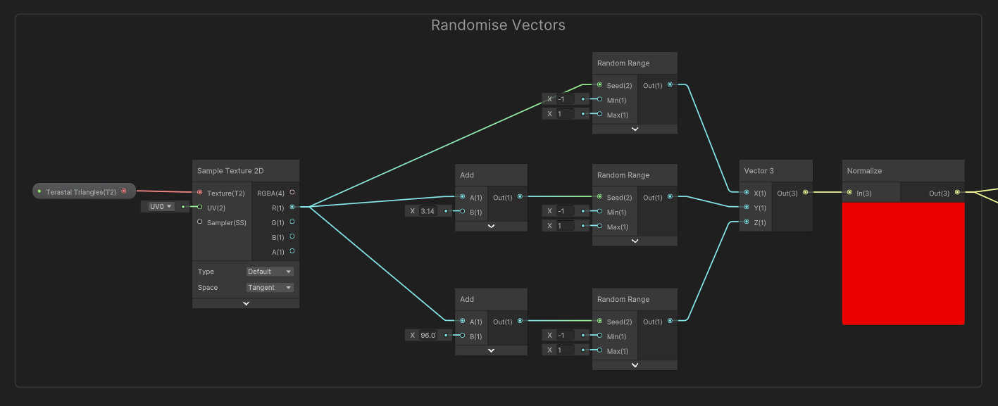
Then, let’s take a Camera node’s Direction value, Normalize it (it might already be normalized? I forgot this step in the video and nothing exploded), and take the Dot Product between it and the vector we just constructed. That’s our basic reflection amount, although we’re going to refine this a lot.
Next, I want to add a way to make the reflections cycle over time even if we just hold the camera still, which will give a bit more life to the idle animation. I’ll add a Float property called Cycle Speed, drag it onto the graph, and multiply it by a Time node. We can just add this to the Dot Product. Next, I’ll multiply it by pi, which can be found using a Constant node, and pass the result into a Sine node. Now, the reflections will cycle on and off over time, and our random triangle values act like an offset for the starting position along the sine wave. I’ll pass the result into a Remap node to change the output range from [-1, 1] to the new range of [0, 1]. 0 means reflection is off, and 1 means it’s fully reflecting.

If we use the reflection values as they currently are, then personally I think there are way too many reflecting triangles (almost every triangle is somewhere in the middle of the 0-1 range) so I want to add a way to reduce the likelihood of a triangle reflecting by adding a threshold. I’ll add a Vector2 property called Reflection Thresholds, which I’m going to use in a Smoothstep node by using a Split node like this:
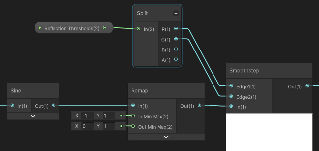
Essentially, any value output by the Remap node that is below the first threshold results in zero reflection. Anything above the second threshold means full reflection. And anything between the two thresholds means a smooth slope between zero and full reflection.
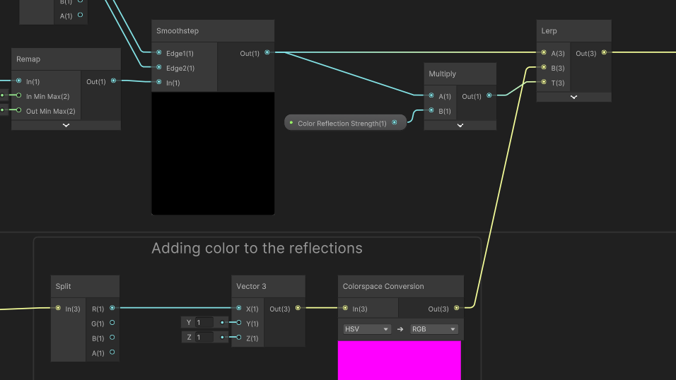
Now, I will add the ability to tint the reflections slightly. I don’t even think that this is something that Pokémon does, but I thought it would be cool and really, that’s what shaders are all about. Let’s add another Float property called Color Reflection Strength - this time, I want to make it a Slider from 0 to 1 so it’s easier to use in the Inspector. I’m going to create a color in the HSV color space - that’s “hue, saturation, and value” - where we have a random hue, but full saturation and value. Let’s go aaaaaall the way back and grab the random triangle vector (the node with the giant red preview in previous screenshots), Split off just the first component, and construct a new Vector 3 with that in the first component and 1 hard-coded into the second and third components. That’s our HSV color. Then, I’ll use a Colorspace Conversion node to turn it back into an RGB color, because that’s what the rest the graph uses.

We can Lerp between the original reflection value (in the A slot) and the fancy new color (in the B slot) using the Color Reflection Strength property in the T slot, but I’m also gonna multiply it by the Smoothstep result because if we don’t, even the triangles that are meant to lack reflections would receive colors which I was trying to avoid.
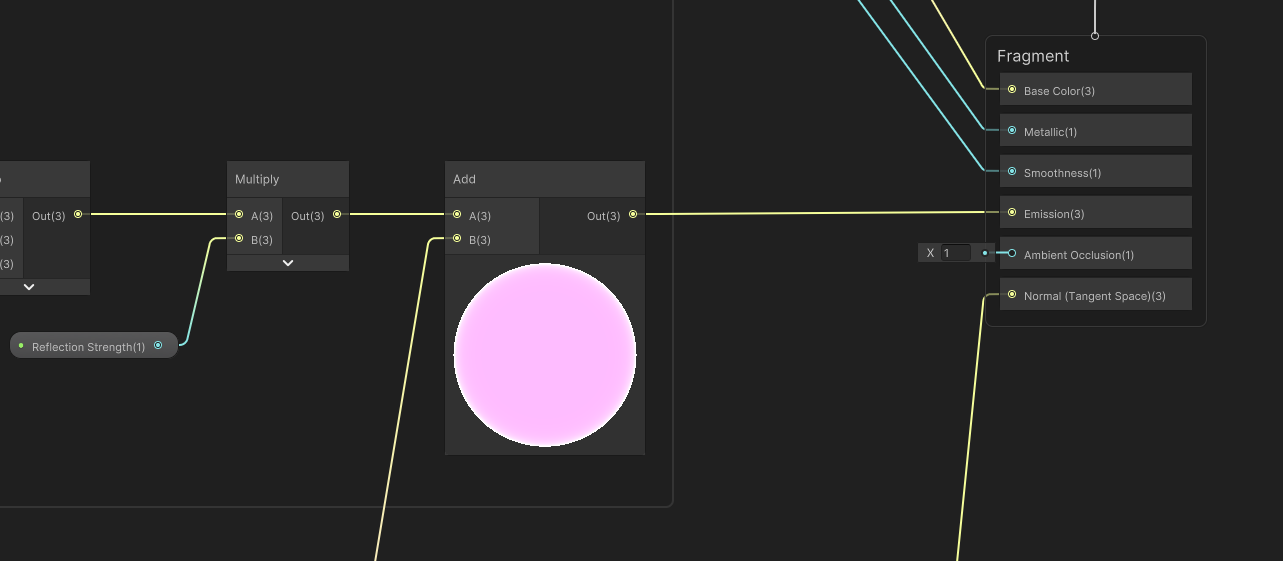
We’re almost done! Next, I want to add a global control for the overall strength of the reflection portion of the shader, so I’ll add a Float called Reflection Strength. I made this a Slider, but between 0 and 10 in case I want to force very bright reflections. Let’s multiply this with the result of that last Lerp we added, and then finally add the Fresnel result from way back earlier in the tutorial.
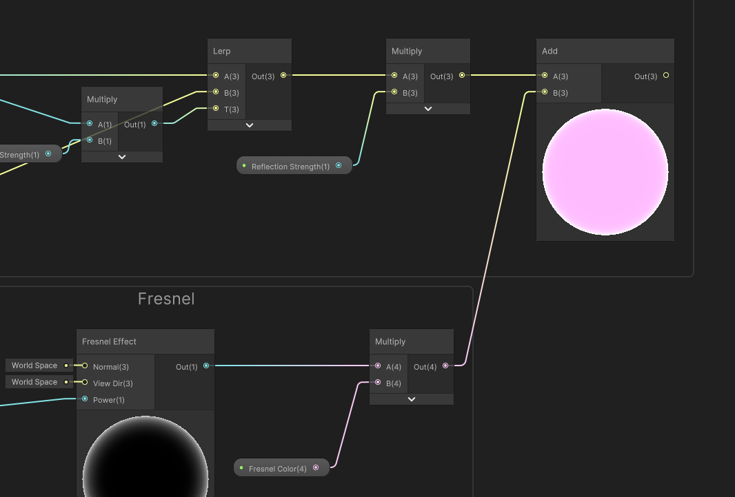
Now, we can pass that into the graph’s Emission output.
And we can see the effect in action on our mesh. Feel free to tweak the properties to get the right mix of reflections and colors you want and now finally, I can…
Terastallize!
My!
Geese!

Until next time, have fun honking. I mean, making shaders.
Subscribe to my Patreon for perks including early access, your name in the credits of my videos, and bonus access to several premium shader packs!
Acknowledgements
Special thanks to my Patreon backers for Apr 2024!
Leonard Rhys Veale-Chan Verisutha Jack Dixon Morrie Mr.FoxQC Pascal pixel_Wing Alexis Lessard claudio croci Jun Lukas Schneider Muhammad Azman Olly J Paul Froggatt Will Poillion Zachary Alstadt 源 刘
