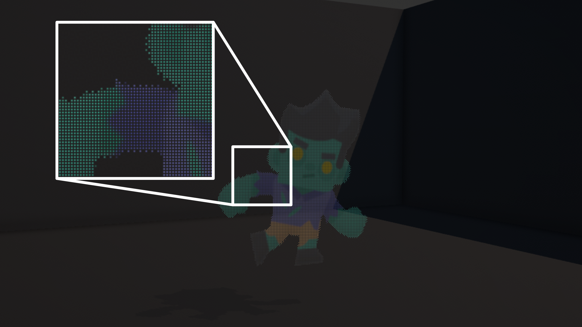
In Part 2, we used textures and UV coordinates to modify the appearance of a couple of basic meshes. In this part, we are going to learn about transparency and alpha clipping. Here is an example of a dithered transparency effect which uses alpha clipping:
Check out this tutorial over on YouTube too!
How Transparency Works
Transparency is handled a bit differently to opaque objects. For efficiency reasons, when rendering opaque objects, you tend to draw them starting with the closest object, because anything behind that object (be it a part-hidden or fully-hidden object) doesn’t need to be drawn at all. It’s obscured by the closer object, and you get an efficiency win.
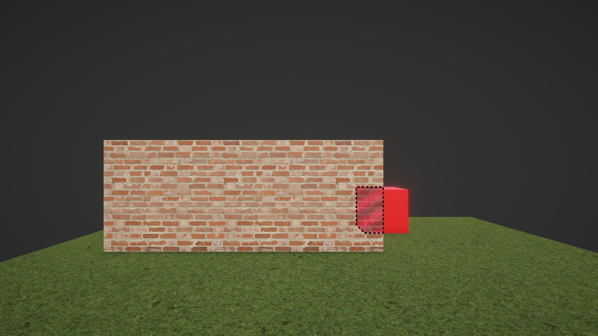
Transparent objects, on the other hand, need to blend their color with the color of the object behind it based on the alpha value of the object. This is called alpha-blended transparency.
First, that means all opaque objects need to be drawn first before any transparent objects are drawn, otherwise we can’t do any color blending. Unity enforces this with a queue system, whereby all shaders are assigned a queue number, and lower numbers are drawn before higher numbers. In code shaders, we specify the number manually, but Shader Graph will handle that for us.
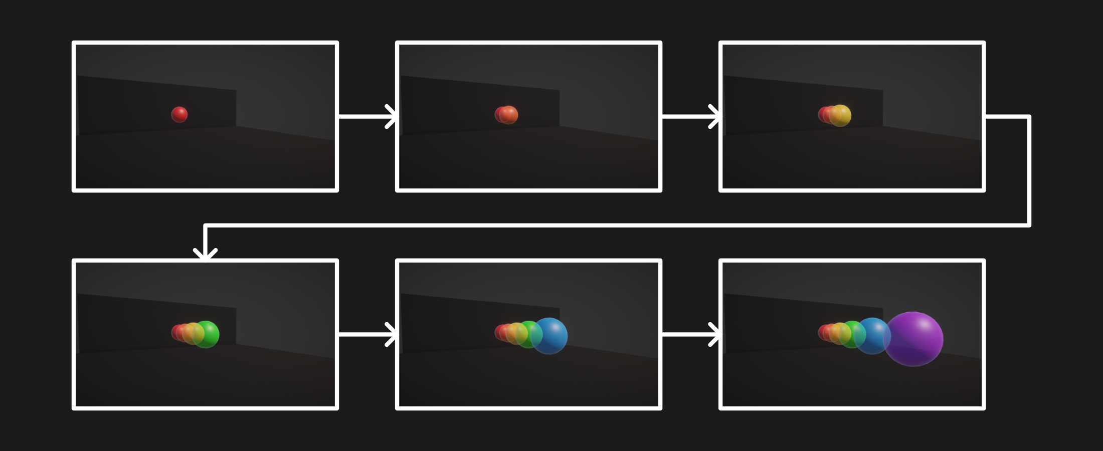
Second, it means that transparent objects are rendered back-to-front, with the furthest objects drawn first, and objects closer to the camera drawn later. This ordering ensures that overlapping transparent objects get their colors blended properly - a front-to-back ordering would give incorrect results.
Transparency in Shader Graph
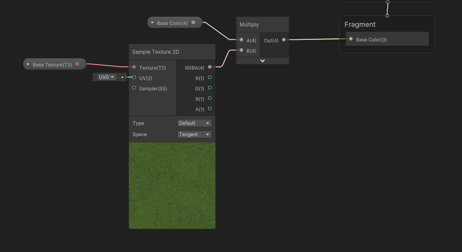
To implement transparency in Shader Graph, I’m going to create a new Unlit graph called “TransparencyExample”. It will look similar to TextureExample from Part 2, minus the scrolling UV functionality for simplicity.
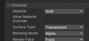
By default, graphs use opaque rendering. To change this, go to the Graph Settings tab on the Graph Inspector, and you will see an option named Surface Type. Change it to Transparent using the drop-down menu, and you’ll see an extra block appear on the output stack called Alpha.
Earlier, I referred to “alpha-blended transparency”. In most image editing tools, you will work with RGBA color values. RGB is easy enough to understand - red, green, and blue - but alpha is sort of this extra, weird value which just means “how transparent the pixel is”. Certain image formats don’t even support an alpha channel - such as JPEG - so make sure you’re using something like PNG, and you’ll be fine.
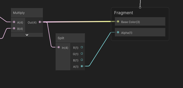
We need to wire something up to the Alpha output. You will notice that the Base Color output takes a Vector3 because of the 3 in parentheses after its name, but we are passing a Vector4 from the preceding Multiply node. This Multiply actually contains an RGBA color, and Unity is automatically truncating the vector - it’s losing that last component when we connect it to something that only expects three components. We need that last component for the Alpha output, so I will drag out a new wire from the Multiply node and add a Split node. As you can see, it splits the Vector4 into its components. We can then wire up the A component to the Alpha output, hit Save Asset, and come into the Scene View.
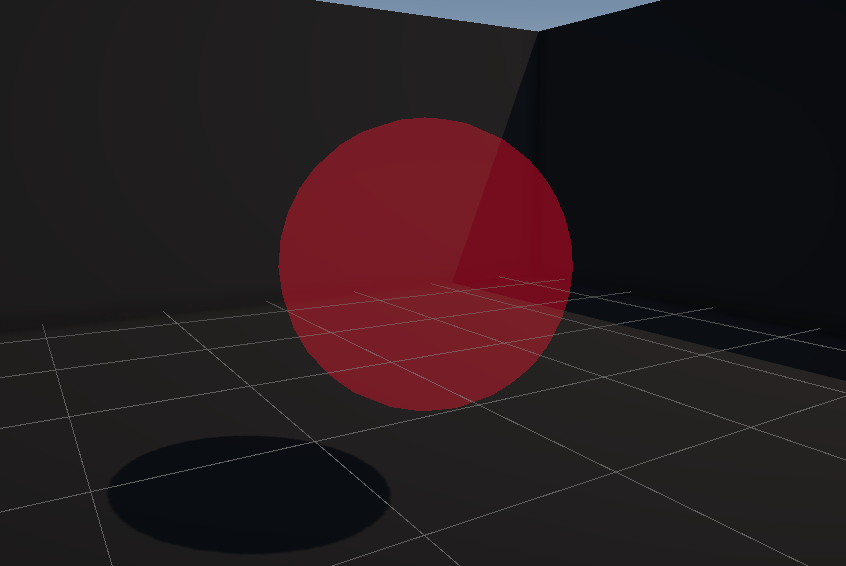
When we attach the material to an object and change the alpha value on the Base Color property, we can see the transparency working as expected.
Subscribe to my Patreon for perks including early access, your name in the credits of my videos, and bonus access to several premium shader packs!
Alpha Clipping in Shader Graph
We’ve now seen basic transparency, but that’s not the only use of alpha. Sometimes you don’t actually want semi-transparency. Sometimes, you just want parts of an object to appear opaque and other parts to be cut away and not rendered, sort of like a visibility mask, or like a cookie cutter. This is where alpha clipping comes in. Alpha clipping can be applied to either transparent or opaque objects, but I’m going to demonstrate it on an opaque object. With alpha clipping, we can set a threshold, and any pixel with alpha below the threshold gets culled - it’s not rendered. Let’s see how it works in Shader Graph.
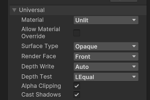
I’ll duplicate the TransparentExample shader and name the new one “AlphaClipExample”. If we go to the Graph settings once more, I’m going to change the Surface Type to Opaque. Then, I’ll tick the Alpha Clipping option box further down the settings list. A new output block called Alpha Clip Threshold will pop up, which is the threshold I mentioned.
I’ll add a new Float property called Threshold and attach it directly to the Alpha Clip Threshold output.
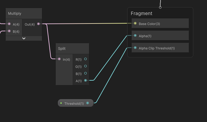
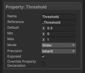
In the Node Settings for the property, we can change the Mode to Slider, which gives us the ability to restrict the range of values we can set for this property. The default Min and Max values of 0 and 1 are perfect.
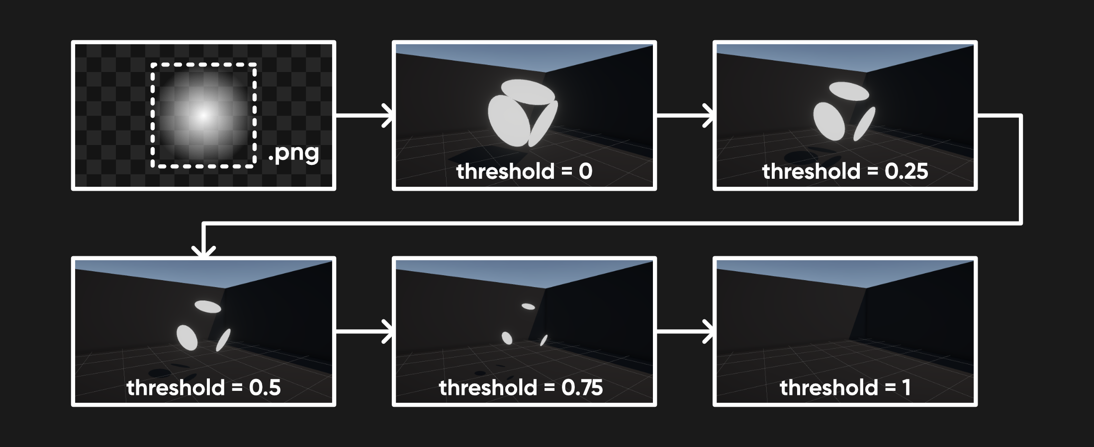
Hit Save Asset again, and in the Scene View, if we use a texture with partial transparency, we can cut it off at different points using the Threshold slider. Nice!
Dithered Transparency
Let’s make one more shader in this tutorial. Full-on alpha-blended transparency can be expensive, especially if you have lots of objects, due to the blending. Opaque objects that use alpha clipping have the ability to cull pixels, but each pixel that is drawn is opaque, so it’s still pretty efficient. There’s a technique I like called dithering where we can fake transparency by culling pixels in a dithered pattern, so on a screen with sufficient resolution, the object still sort of appears transparent.

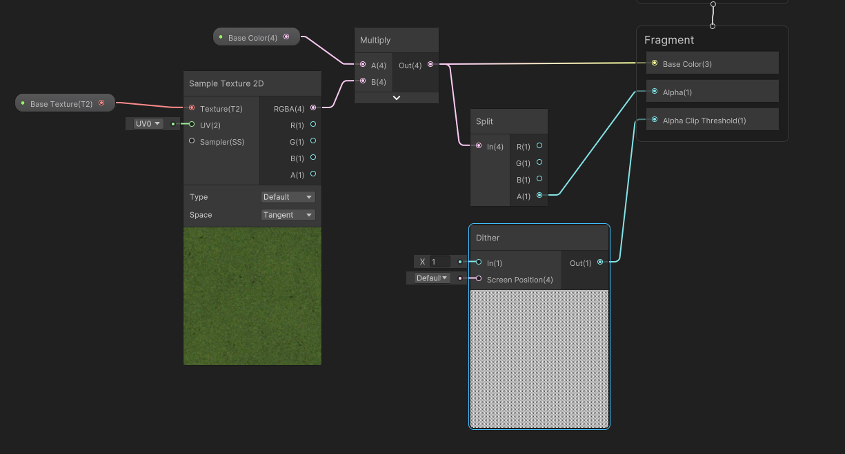
Let’s see it in action in Shader Graph. I’ll start by duplicating the AlphaClipExample shader and name the new one “DitherExample”. I’ll get rid of the Threshold property and delete the node going into Alpha Clip Threshold. Shader Graph has a Dither node which I’ll add - it generates a dither pattern as you would expect.
If we change the In value to 1, you’ll see the pattern in the preview (it’s a bit blurry when you zoom in, so here’s a crisp version):

You will also notice that it takes a screen position as its second parameter, rather than a UV coordinate. That means this pattern will be applied in screen space, rather than over the surface of the object. That’s perfect for our use case! We can wire this node directly to the Alpha Clip Threshold output, hit Save Asset, come back to the Scene View, and now if we play around with the alpha component of the Base Color property, the object sort of looks like it’s fading out, but every pixel that is being rendered is still opaque! How about that.
Conclusion
We learned a lot about how Unity renders objects, and used that to make some transparency shaders. In the next part, we’ll learn a bit more about how opaque objects work by looking at the depth buffer. Thanks for reading!
Subscribe to my Patreon for perks including early access, your name in the credits of my videos, and bonus access to several premium shader packs!
Acknowledgements
Special thanks to my Patreon backers for Sep - Nov 2023!
JP SungHoon Kang Verisutha Jack Dixon Morrie Mr.FoxQC Josh Swanson Leonard pixel_Wing Alexis Lessard beany claudio croci dmitrii-t Hassan Karouni Jau Liu Jun Mikel Bulnes Ming Lei Muhammad Azman Olly J Paul Froggatt Ray J Will Poillion Zachary Alstadt 源 刘
