In Part 1, we saw how we can use Shader Graph to control the color of objects. In Part 2, we will use textures to give ourselves essentially infinite control over the appearance of the surfaces of objects.
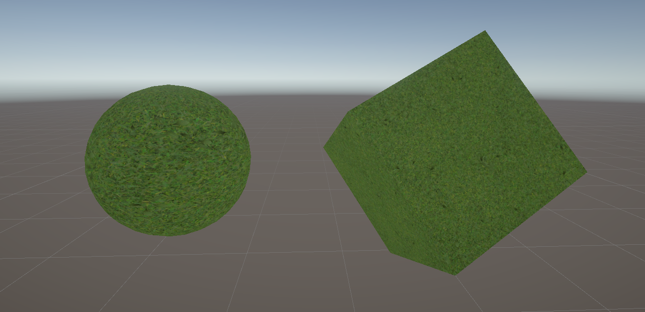
Check out this tutorial over on YouTube too!
What is a Texture?
A texture is basically just an image. It’s a 2D array of color values, and we can apply those color values to objects in lots of different ways. Usually that involves mapping the 2D texture to a 3D object and just painting the object with those colors, but there are many other ways to use textures:
- Use a color gradient texture and apply it to objects based on their y-coordinate.
- Pack a spritesheet animation into a single texture and flick between each individual sprite within the sheet.
- Use normal maps to modify the way lighting interacts with the surface of the object.
However, I’m getting very far ahead of myself here. Let’s focus on the basics to start with.
Where Do I Get Textures?
That’s a good question! Basically, when a mommy artist and a daddy artist love each other very much… no, I can’t say that. Textures come from many places. You can make them yourself using a program like Photoshop, GIMP, Krita or similar, but there are free sources of textures online. My favorite sources are ambientCG, which hosts a bucketload of realistic textures for 3D, and Kenney, who creates an absolute deluge of sprites for 2D, alongside other assets. Both sources use the CC0 license for most assets, which means we’re free to use them for funsies or for commercial projects.
I’ll grab this grass texture from ambientCG, but you can use any texture you want.

Using Textures in Shaders
Let’s build on our work from Part 1 by duplicating the ColorExample shader and naming the new one TextureExample. This graph has the Base Color property from before, but I want to blend that color together with the grass texture I downloaded. I’ll add a second property to the graph with the Add button, and this time the property type is Texture 2D. Let’s name it Base Texture. Over in the Node Settings window, we can choose a Default texture, so I’ll click the small circle next to the field and find my texture in the dialog window that appears.
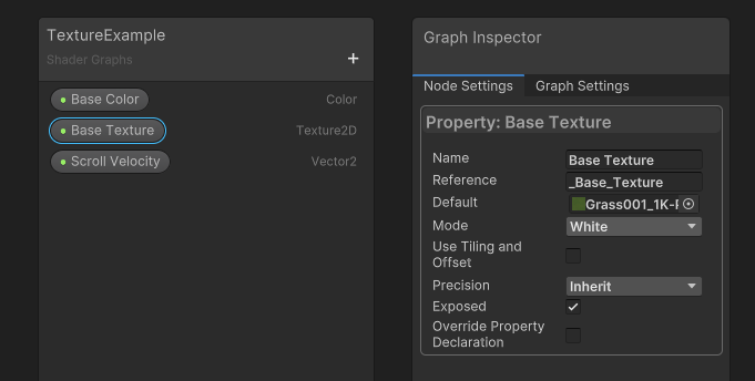
As we did with the Base Color property, we can drag Base Texture onto the graph. However, Shader Graph will not let you connect the texture node to the Base Color graph output yet. When it comes to textures, we need to tell Unity which position on the texture we should read data from. To do this, models have some attached data called UV coordinates, which are a mapping between vertices of the mesh and positions on a texture in a range between 0 and 1 on the X and Y axes (or the U and V axes, hence “UVs”). For parts of the model between vertices, we can blend between the UVs of the nearest vertices.
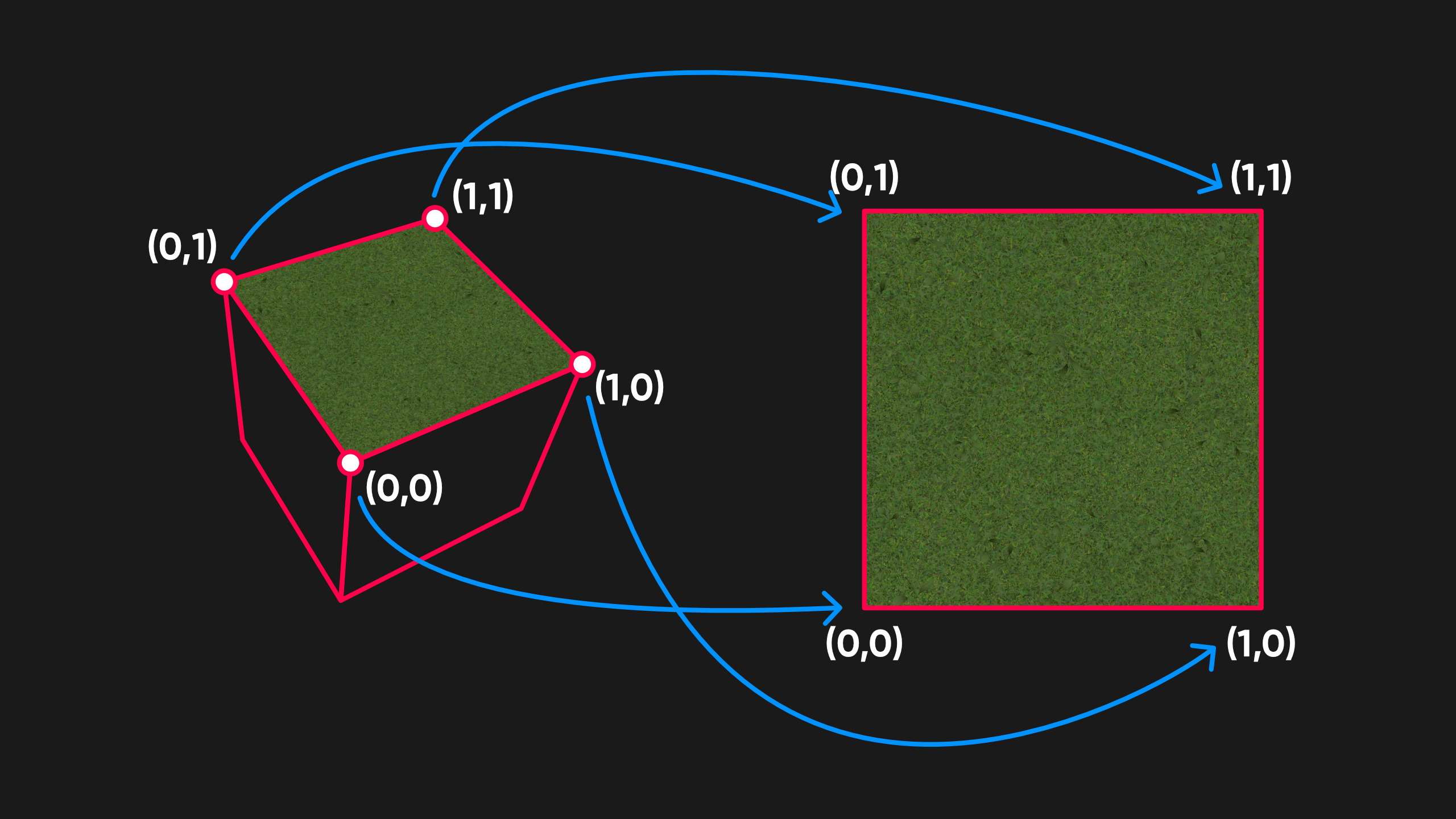
Setting up UVs on your own custom models is outside the scope of this tutorial, but Unity’s primitive meshes do have UVs set up for you already. The cube slaps the full texture onto each of its six faces, while the sphere tries to wrap the texture around its equator, becoming very warped around the north and south poles.
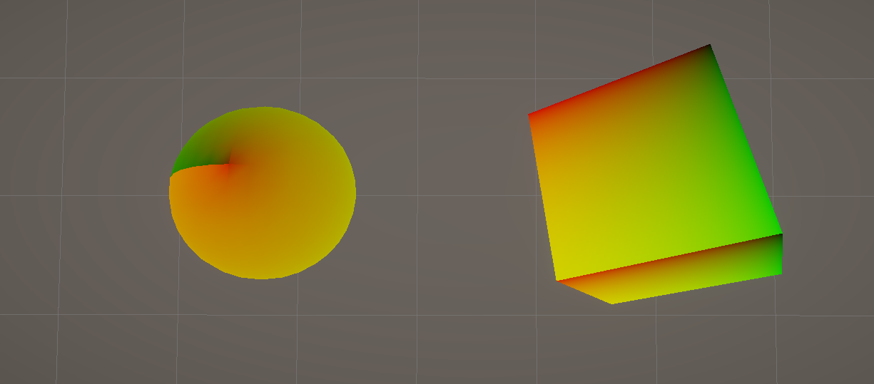
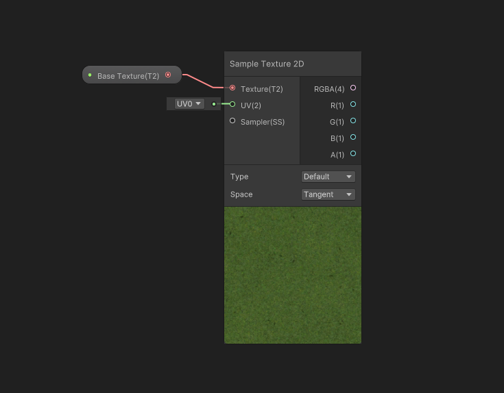
To read textures using a UV coordinate, we use a node called Sample Texture 2D. To add new nodes onto the graph, you can right-click and pick Create Node, or you can just press the spacebar anywhere on the graph. Type “Sample Texture 2D” into the search bar and pick the node from the list - just be careful because there are many similarly named nodes.

This node appears a lot more complicated than the other nodes we’ve seen so far, but don’t be intimidated. On the left, it takes a texture as input (we can go ahead and attach our Base Texture to it) and a set of UVs. By default, it uses UV0, which is the first set of UVs attached to the mesh - they can have multiple. UV0 is the channel where Unity stores the UVs for the primitive meshes I mentioned earlier. Basically, we don’t need to attach anything to this input for now.
The node also has several outputs: the top one, RGBA, is the full color you get when you sample the texture, and the other four outputs are just the individual red, green, blue, and alpha/transparency components of that RGBA color.
To combine this texture and the Base Color from Part 1, we can multiply the two together with a Multiply node. This is the simplest way to combine colors: take both red values and multiply them together, then take both green values and multiply them together, and so on. The result of that Multiply node can be outputted to the Base Color output block.
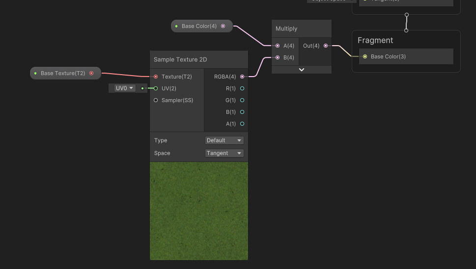
Remember to click Save Asset in the corner before you return to the Scene View to check out the shader in action.

Subscribe to my Patreon for perks including early access, your name in the credits of my videos, and bonus access to several premium shader packs!
Scrolling Texture Coordinates
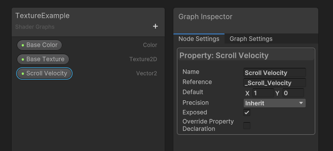
Now that we have successfully sampled a texture, let’s do something a bit more exciting with it. UVs don’t always come solely from data attached to a mesh. In fact, you can generate UVs of any kind within the shader if you want. In this next example, I’m going to scroll the UVs over time in whichever direction you want. For this, I will add a new Vector2 property and name it Scroll Velocity. This property lets us control the direction and speed of the scrolling, and it’ll have a default value of (1, 0).
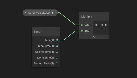
We already saw that the Sample Texture 2D node takes a UV as input, so we will be slotting something into this input. Let’s drag the Scroll Velocity onto the graph, then right-click and add a Time node. Time is one of the most common nodes I use, as it is extremely helpful for animating your shaders. It provides several kinds of time value, but the one you’ll probably use most often is just labelled “Time”, which is the number of seconds since the scene was loaded. By multiplying Time and Scroll Velocity, we end up with a vector that grows in the same direction over time. The result is an offset vector which we can apply to the mesh’s default UVs (the UVs we currently use to sample the texture).
Luckily, Shader Graph has a node which makes it very easy to apply offset vectors like this: Tiling And Offset. If we connect the output of the Multiply node to the Offset field, then the node calculates a new set of UVs with the offset applied. It’s a similar story if we change the Tiling input value: it will zoom in or out of the texture. We can leave the Tiling values at 1, though.
The final step is to attach the output from the Tiling And Offset node to the UV input on the Sample Texture 2D node. The preview window on the sampling node will start to scroll, as long as Scroll Velocity uses a default value other than (0, 0). Seeing your changes live in the Shader Graph window is one of the most powerful features of this tool, as it allows for rapid prototyping. You can always see, at a glance, what effect any given change will have on the resulting shader.
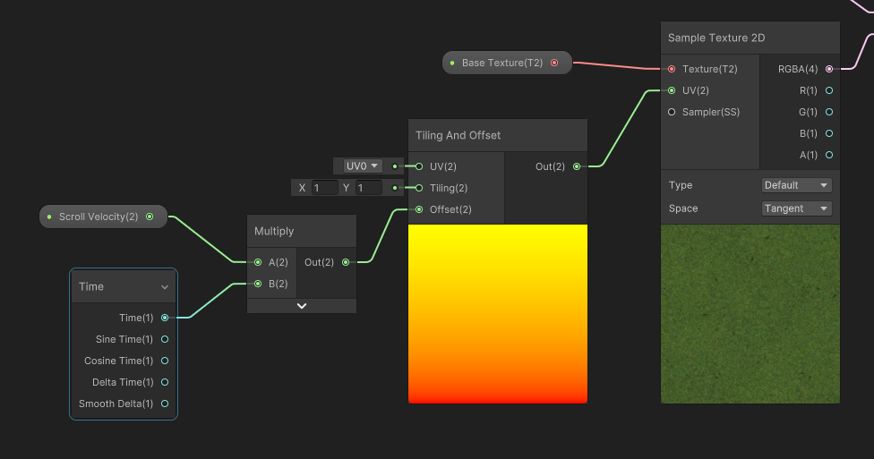
Hit Save Asset and check out the Scene View to see your textures scrolling across the mesh (which might look strange on the seams between faces).
Conclusion
We’ve learned a bit about textures and UVs today! In the next part of the series, we’ll look at transparency and alpha clipping. Thanks for reading!
Subscribe to my Patreon for perks including early access, your name in the credits of my videos, and bonus access to several premium shader packs!
Acknowledgements
Special thanks to my Patreon backers for Sep - Nov 2023!
JP SungHoon Kang Verisutha Jack Dixon Morrie Mr.FoxQC Josh Swanson Leonard pixel_Wing Alexis Lessard beany claudio croci dmitrii-t Hassan Karouni Jau Liu Jun Mikel Bulnes Ming Lei Muhammad Azman Olly J Paul Froggatt Ray J Will Poillion Zachary Alstadt 源 刘
