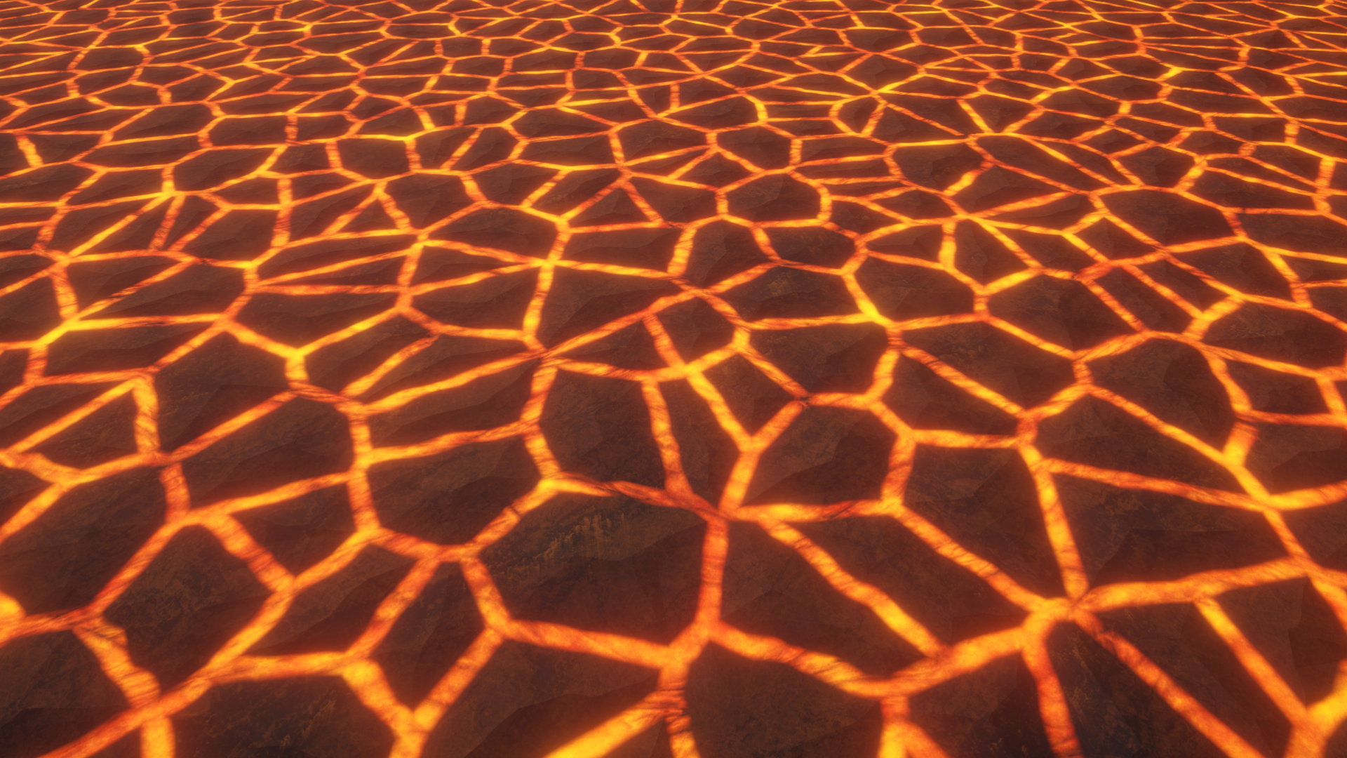
Voronoi diagrams are a very versatile tool for technical artists, as they resemble natural shapes like biological cells or rocks. The 3D equivalent is even used for destructible geometry. They also excel at creating lava that flows between islands of rock, which is what we’re going to make in this tutorial, with emissive, animated lava streams.
Check out this tutorial over on YouTube too!
Voronoi Function
Voronoi works by distributing control points onto a plane, then for each position on the plane, we work out what the closest point is and do something with that information. Sometimes people color each pixel based on which control point is closest, and other times people color each pixel based on the distance from the closest point. We’re going to color pixels based on the distance from the closest boundary between regions, which is a bit more difficult but definitely doable in Unity.
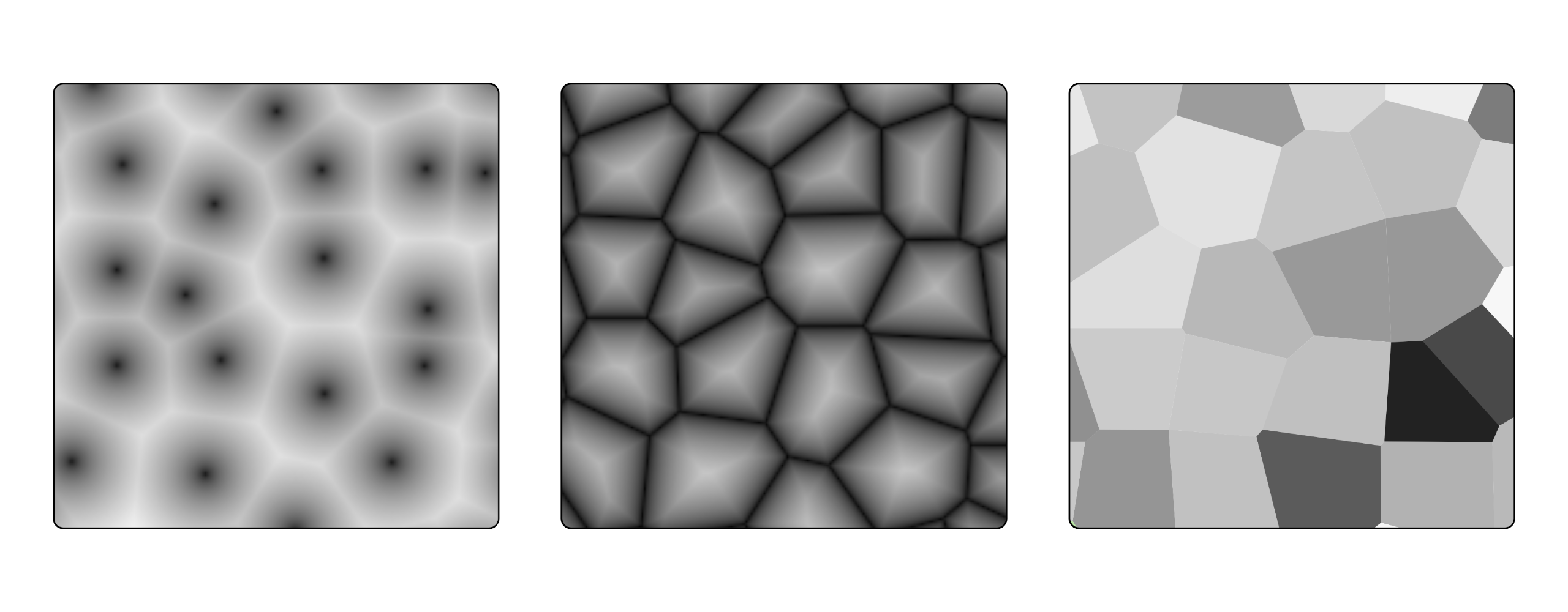
Shader Graph comes with a Voronoi node, which outputs two things: the distance from the nearest control point, and a random value for each region. However, it doesn’t output any information about the edges separating those regions. You can try and extract information about the edges, perhaps by using a DDXY node (which finds gradients between adjacent pixels) but that looks pretty bad, and you can’t customize the width of those edges at all.
To get this edge information, we’ll need to write our own custom Voronoi node with an HLSL file, which you’ll need to create with an external text editor - just make sure you give the file the “hlsl” extension. Don’t worry if you don’t want to write any code yourself - it’s in the GitHub. My custom node will output the distance from the closest control point and the distance from the closest edge, but not the random value for each region which Shader Graph’s Voronoi outputs.
CustomVoronoi.hlsl
I’m basing this on code by Inigo Quilez, a fantastic shader person who’s been doing this longer than I’ve been alive. Essentially, we divide the whole plane into ‘cells’ of equal size and generate a random control point within each cell, using the lower-left corner position of the cell as a random seed. Every time you input the same corner position into the random function, you get the same control point position. I stole the random function from Shader Graph’s built-in Voronoi node implementation.
inline float2 randomVector (float2 UV, float offset)
{
    float2x2 m = float2x2(15.27, 47.63, 99.41, 89.98);
    UV = frac(sin(mul(UV, m)) * 46839.32);
    return float2(sin(UV.y*+offset)*0.5+0.5, cos(UV.x*offset)*0.5+0.5);
}

// Based on code by Inigo Quilez: https://iquilezles.org/articles/voronoilines/
void CustomVoronoi_float(float2 UV, float AngleOffset, float CellDensity, out float DistFromCenter, out float DistFromEdge)
{
    int2 cell = floor(UV * CellDensity);
    float2 posInCell = frac(UV * CellDensity);

    DistFromCenter = 8.0f;
    float2 closestOffset;

    for(int y = -1; y <= 1; ++y)
    {
        for(int x = -1; x <= 1; ++x)
        {
            int2 cellToCheck = int2(x, y);
            float2 cellOffset = float2(cellToCheck) - posInCell + randomVector(cell + cellToCheck, AngleOffset);

            float distToPoint = dot(cellOffset, cellOffset);

            if(distToPoint < DistFromCenter)
            {
                DistFromCenter = distToPoint;
                closestOffset = cellOffset;
            }
        }
    }

    DistFromCenter = sqrt(DistFromCenter);

    DistFromEdge = 8.0f;

    for(int y = -1; y <= 1; ++y)
    {
        for(int x = -1; x <= 1; ++x)
        {
            int2 cellToCheck = int2(x, y);
            float2 cellOffset = float2(cellToCheck) - posInCell + randomVector(cell + cellToCheck, AngleOffset);

            float distToEdge = dot(0.5f * (closestOffset + cellOffset), normalize(cellOffset - closestOffset));

            DistFromEdge = min(DistFromEdge, distToEdge);
        }
    }
}
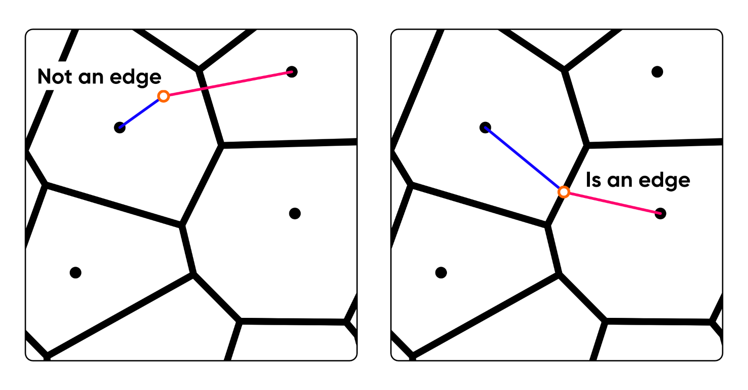
I won’t go into too much detail line-by-line, but the general idea of the code is this. We run two passes over the cells. We first set a DistanceFromCenter variable to an arbitrarily large value, then the first pass runs over a 3x3 section of cells, where the center cell contains the current pixel. We check the distance between the pixel and the control point for each cell, and if the distance is less than DistanceFromCenter, we overwrite DistanceFromCenter. Crucially, we also remember what the offset was - this will be important later. After the loop finishes, DistanceFromCenter gives us basically the same information the original Voronoi node does.
The second loop attempts to find the second closest control point in order to compare the distance with the first distance which we remembered. We start by setting DistanceFromEdge to an arbitrarily large value, then we run another loop over the same 3x3 cell grid. One of the key parts is this line:
float distToEdge = dot(0.5f * (closestOffset + cellOffset), normalize(cellOffset - closestOffset));
The normalize function here will evaluate to infinite if cellOffset and closestOffset are the same value, which only happens if the second loop is check the closest control point. That’s because normalizing a zero vector is undefined. But we want to filter it out because we’re trying to find the second closest control point. That’s useful because it means the line evaluates to a large number and we just move to the next loop iteration. It’s an ingenious technique by Inigo! Otherwise it’s similar to the first loop - we’ll overwrite DistFromEdge if we’ve found a new smallest distance.
Creating the Graph
Now it’s time to incorporate this code into Shader Graph somehow and make the lava effect with it. In Unity, I made a new graph via Create -> Shader Graph -> URP -> Lit Shader Graph (although the Lit graph equivalent in any render pipeline should be fine) and named it “Lava”. Inside the graph, I’ll begin by adding a Custom Function node, going to its Node Settings, and wiring up the CustomVoronoi.hlsl file in the Source slot, typing the name of the function we wrote minus the “_float” (so, “CustomVoronoi”) into the Name field, and setting up the inputs and outputs like so:
- A UV input of type
Vector2. - An AngleOffset input of type
Float. - A CellDensity input of type
Float. - A DistanceFromCenter output of type
Float. - A DistanceFromEdge output of type
Float.
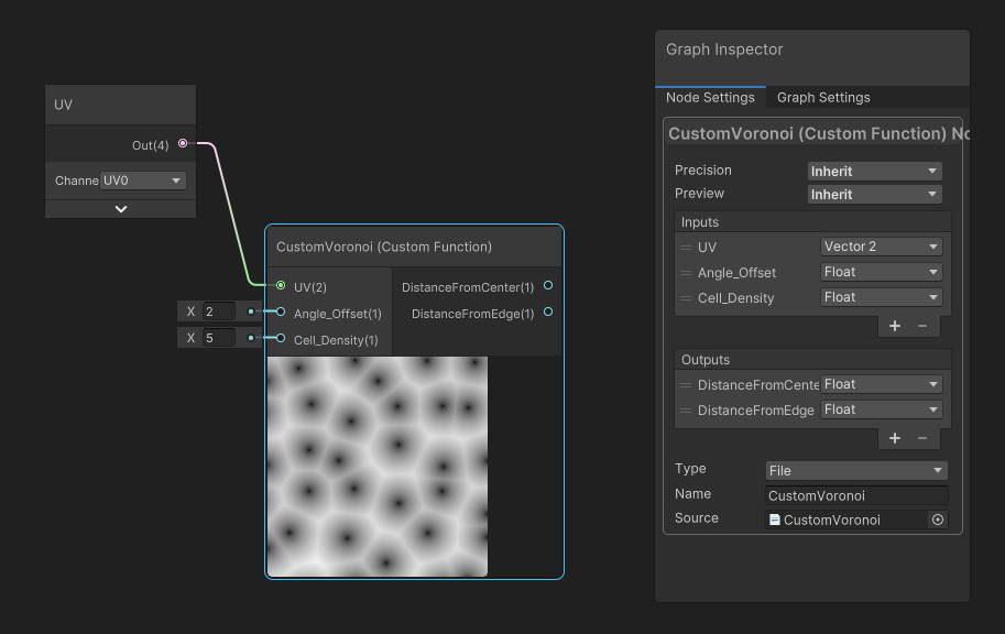
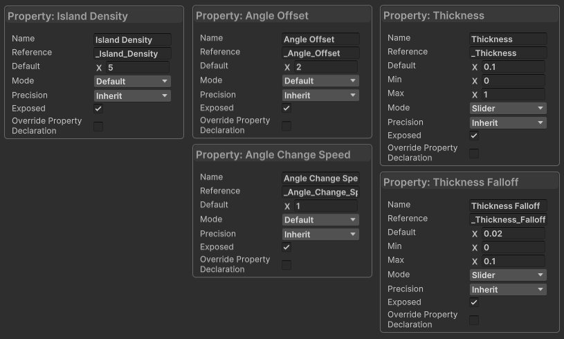
We’ll work outwards from here, as there are nodes that come before and after this one. For the shape of the rock ‘islands’ and the width of the lava channels, we’ll need five graph properties, all of which are of type Float:
Island Densitycontrols the size of the cells used in the Voronoi calculations, which in turn impacts the physical size of the rock islands.Angle Offsetcontrols how far the cell control points move from some start point. If it is zero, then we’ll have a regular grid of points.Angle Change Speedcontrols how quickly the Angle Offset increases, so we can animate the island shape by setting it above zero.Thicknessrefers to the width of the lava channels.Thickness Fallofflets us blend the lava and rock regions together so the transition isn’t a hard boundary.
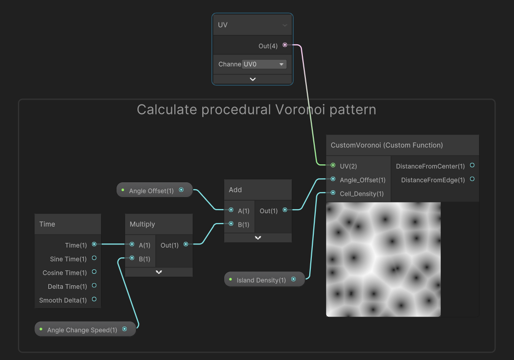
For our CustomVoronoi node’s Angle Offset input, let’s multiply our Angle Change Speed property by Time, then add the result to the Angle Offset property. For its Cell Density input, we can use the Island Density property. For now, I’ll stick a UV node into the UV slot so that we can see something on the preview window of the CustomVoronoi node, but we’ll do something more complicated with the UVs later.
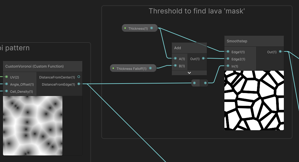
Next, we’ll apply a threshold to the DistanceFromEdge output in order to create a ‘mask’ separating rock regions from lava regions. The threshold will have a small amount of falloff so that there is a transition zone where rock melts into lava, so I’ll use a Smoothstep node. For its Edge1 input, I’ll use the Thickness property, and for Edge2, I’ll use Thickness plus Thickness Falloff. Then, for the In value, I’ll use the DistanceFromEdge output from the CustomVoronoi node. Now we have our mask.
Now we will go back and modify the UVs we used for CustomVoronoi. Even if you decide to set Angle Change Speed to zero, I want there to be some animation where the lava channels wiggle a bit to give the impression that there are temperature gradients within the lava causing movement. I’m no geologist, but I think that sounded technical enough.
Let’s add three more properties:
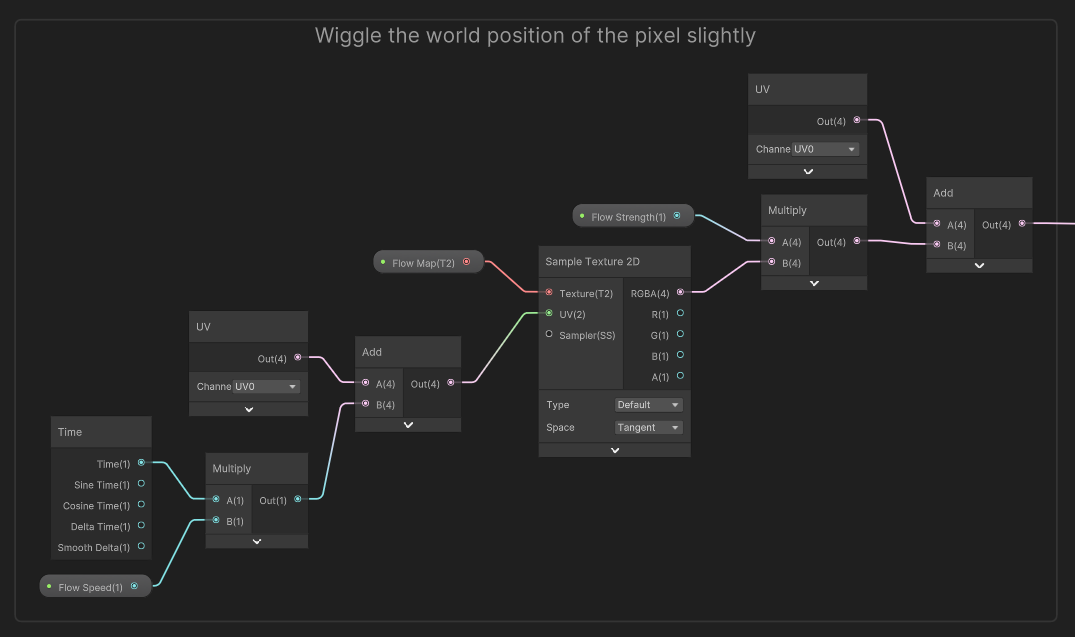
Flow Mapis aTexture2Dwhich contains directional information encoded within the red and green channels of each pixel.Flow Strengthis aFloatwhich represents how far the lava gets displaced from its original position.Flow Speedis aFloatwhich represents how fast the shader scrolls through theFlow Map.
It’s important to enable Use Tiling and Offset for the Flow Map in its Node Settings because I want to tile the texture.

Let’s multiply the Flow Speed by Time and add it to a UV node, then use the result to sample the Flow Map texture. This collection of nodes will scroll the Flow Map over our mesh, but we’re not doing much with it yet. Each pixel of this texture contains a 2D offset value I want to add to the UVs I use for the CustomVoronoi node, so I’ll multiply the result of the Sample Texture 2D node by the Flow Strength property and add it to another UV node. This is the value I use for the CustomVoronoi UV input, and now our lava can wiggle.
There are three more things left to add to the graph: the rock colors, the lava colors, and changing the lighting on the rocks with a normal map. Let’s start with the rocks.
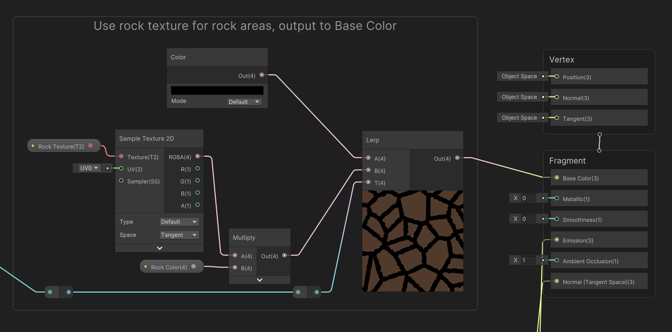
We need two more properties: a Rock Color and a Rock Texture. The rock texture (and the upcoming lava texture) are from ambientcg.com, a wonderful resource for CC0 textures. I’ll take the Smoothstep mask we created previously and use it for the interpolation factor T input of a Lerp node. To recap, Lerp nodes can slide their output value between two input values, A and B, depending on a third input, T, which is between 0 and 1.
For the B slot, we’ll input the color black, because the mask labels the lava areas with the value 1, so we don’t want to color these bits with the rock texture. For the A slot, the mask values are labelled 0 on the mask and are therefore rock areas, so we’ll sample the Rock Texture and multiply it by the Rock Color. The output from Lerp can be connected to the graph’s Base Color output because we want these parts to use regular lighting.
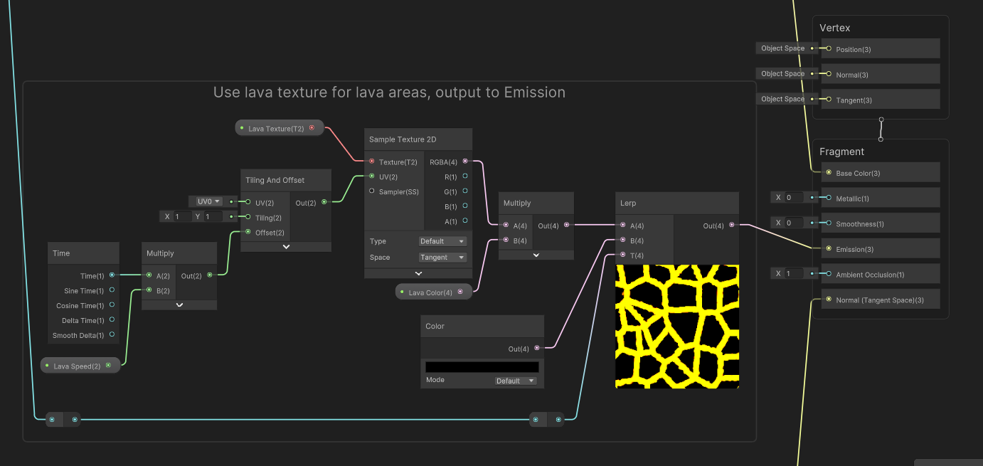
For the lava, we’ll add Lava Color and Lava Texture properties, but we’ll also add a Lava Speed Vector2 which allows us to scroll the lava texture to make it appear as if the lava is travelling through the lava channels. The Lava Color should also have HDR enabled in its Node Settings.

Like how we dealt with the rock areas, I’ll use the Smoothstep ‘mask’ in a Lerp node T slot. This time, the B input should be black because those are the rock areas which we don’t want to apply the lava colors to. For the A slot, we’ll sample the Lava Texture and multiply its RGBA output by the Lava Color, but unlike the rock colors, we’ll also modify the UVs we use to sample. Take the Lava Speed and multiply by Time, then connect its result to the Offset slot of a Tiling And Offset node, then use that result in the UV slot of the Sample Texture 2D node. The result of the Lerp should be connected to the Emission graph output, which means it will always be visible, even if the lava is placed in an otherwise dark cave, or anywhere at night.
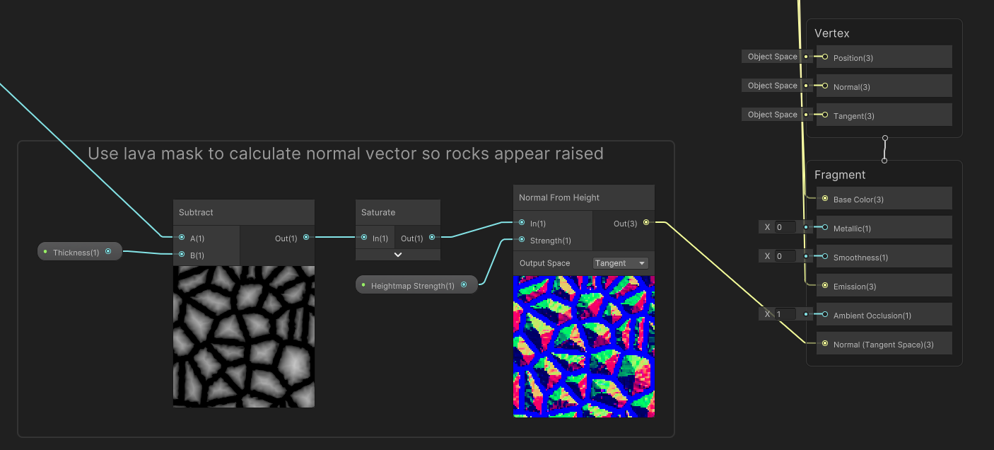
That just leaves the normal vector we wanted to modify. Currently, the rocks are all flat, so it would be nice to add some shape to them, and the easiest way I could think of is to add a normal map to them. You could feasibly add a physical offset to the vertices, but that would require a much higher-poly mesh and a lot more nodes on the graph, so I decided against doing that. I’ll generate the normal map by turning the CustomVoronoi output into a heightmap.
Add a new Float property called Heightmap Strength. Then, take the DistanceFromEdge output of the CustomVoronoi node and subtract the Thickness property - now, all the lava areas will have a negative output and the rock areas have a positive output. With a Saturate node, those negative values are clamped to zero, so it’s as if all the lava is flat and all the rocks rise up slightly. Use a Normal From Height node using the Saturate output and the Heightmap Strength property to generate the normal map, which looks pretty trippy on the node preview, and connect its output to the Normal block on the output stack. You’ll also need to set the Smoothness output to 0, because a value above that would have strange lighting.
In the Scene View, you’ll now be able to see the lava pattern on any objects using the Lava shader in its material. You may need to tweak the material values depending on the size and shape of the mesh you’re using, and if you want the lava to glow, you will need to set up a Bloom post processing filter in your scene, which is possible in all Unity pipelines (and is set up for you in most of the scene templates for URP and HDRP).
Subscribe to my Patreon for perks including early access, your name in the credits of my videos, and bonus access to several premium shader packs!
Acknowledgements
Special thanks to my Patreon backers for May - June 2023!
Bo JP Jack Dixon kai Morrie Mr.FoxQC Josh Swanson Leonard Moishi Rand Alexis Lessard claudio croci Jay Liu Mikel Bulnes Ming Lei Muhammad Azman Olly J Paul Froggatt Will Poillion Zachary Alstadt 源 刘
