Since URP launched a few years ago, it’s been tricky to create custom post processing effects for that pipeline. The next major Unity version promises to make things a lot easier with the inclusion of the new Fullscreen Shader Graph, which lets you produce effects which run over the screen after the camera has rendered all objects. You’ll be able to make any number of funky effects, and in this tutorial, I want to try out the Fullscreen Shader Graph option in Unity 2022.2, before the next Long Term Support version lands. All the assets for this project are available on GitHub as usual.
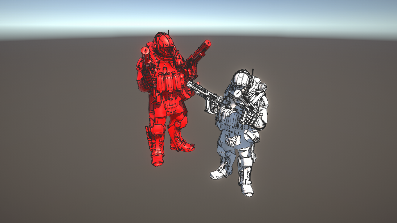
This tutorial uses Unity 2022.2.8f1 and URP 14.0.6, so there may be changes when Unity 2022 LTS comes out. Check out this tutorial over on YouTube too!
Introduction
Post Processing effects work by taking the output of a camera once all objects have been rendered - you may usually think of color data, but this includes normal data, depth data, and so on - and applying some combination of effects to that data to produce a new color output. One example is color grading, which performs a mapping between one set of colors and another, and another is noise grain, which generates noise values and overlays them onto the original image. In this article, I will be using an edge detection technique to find boundaries between objects, then I will overlay thin outlines onto those edges.
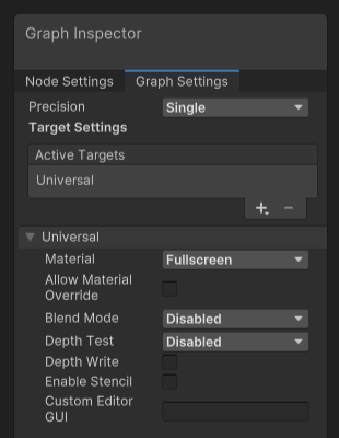
Start by right-clicking in the Project View, then select Create -> Shader Graph -> URP, and you will see a brand new option called Fullscreen Shader Graph. Upon opening the graph, in the Graph Settings, you will see the Material option is set to the new Fullscreen mode (this is the same drop-down which includes familiar options like Lit and Unlit).
On the graph surface, we will grab information from the camera by using a brand new node called URP Sample Buffer. It has three options in its Source Buffer drop-down: NormalWorldSpace gets the normal vector at every pixel of each surface in the scene; MotionVectors gives us a vector representing how far any given object moves between frames; and BlitSource gives us the color of every object.

The MotionVectors mode can be hard to visualize in a still image so you might want to try it out on your own!
Normal-based Edges
Let’s think about how we can use only this information to detect edges. An edge should appear anywhere on a boundary between two objects (or different parts of one object), so for each pixel in the image, we should check the adjacent pixels, and if they have a significantly different color from the center pixel, we can mark the pixel as an edge and give it an outline. This technique works well if your game uses blocky colors, although it may not perform as well with highly textured objects. Likewise, we can detect large differences between the normal vector of a pixel and its adjacent pixels. Although the following screenshot shows a 3x3 grid, you can detect edges in a cross-shape pattern ignoring the corners of the grid (as I’m going to do in this article) or use a larger or smaller grid (look up the Sobel operator or the Roberts cross operator for more information).
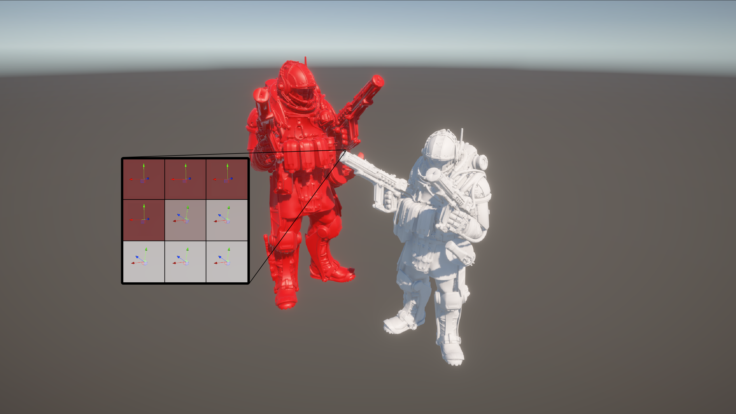
I’ll begin working on the graph by detecting normal-based edges, so I’ll set the URP Sample Buffer source to NormalWorldSpace. This node takes a UV coordinate as input, which by default is equivalent to inputting a Screen Position node. If we want information about an adjacent pixel instead, then we’ll need to add an offset of (1/screen pixel width) in the x-direction, or (1/screen pixel height) in the y-direction.
I’m going to do four samples with four offsets: up, down, left, and right from the center pixel. Each one requires its own URP Sample Buffer node. Take the result of the left and right samples and subtract one from the other, then use a Length node to give us a measure of how much the normal vector changes in the x-direction over the center pixel. Then, do the same thing with the up and down samples. By adding the x-result and y-result, we get a value representing the total difference in normals over the center pixel.
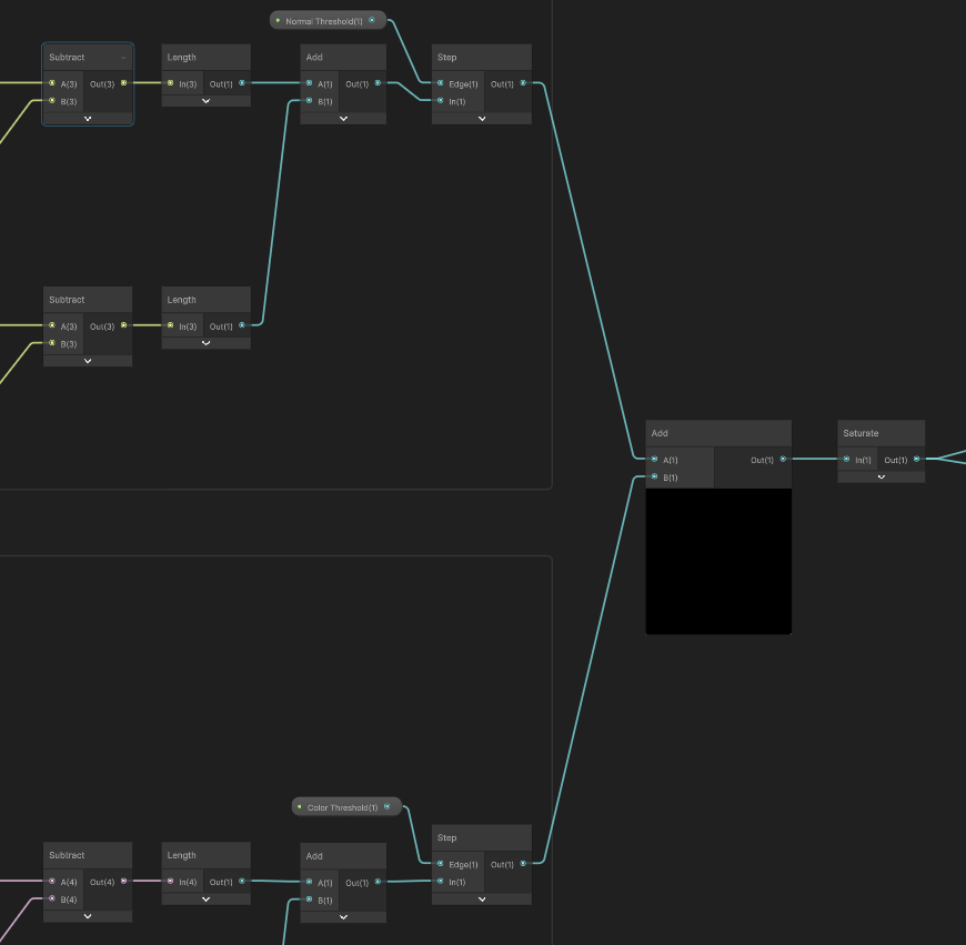
Next, I’ll add a Float property called Normal Threshold, which should take values clamped between 0.001 and 10. A value of 0 would break the effect, because every pixel would end up registered as an edge, while 10 is a good maximum value because it filters out practically all the edges. Use a Step node to apply the threshold to the total normal difference value, and now we should have a value of 1 wherever an edge was detected, and 0 everywhere else.

If I continued the graph to the end from here (there’s more to come so I’ll show you how in a bit), then I would end up with pretty decent outlines, but it’s unable to distinguish between any two adjacent faces with the same normal vector but a different color. With that in mind, let’s add color-based edge detection to the graph.
Color-based Edges
Color-based edges use almost exactly the same nodes as normal-based edges. In fact, I’m going to copy everything we’ve done so far and drag it down a little, then change all four URP Sample Buffer nodes to use BlitSource mode instead. I’ll also add a Color Threshold Float property with values between 0.1 and 10 (values below 0.1 have a very strange visual appearance) and swap it out with the Normal Threshold property that we copied.
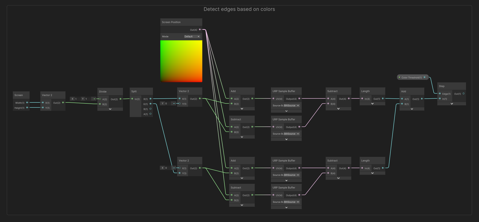
Now, when we add the two Step outputs together and Saturate the result, we end up with a value of 1 when the pixel is either a normal-based or color-based outline (or both), and 0 if it is not an outline.
The graph is almost complete, so now let’s deal with the graph outputs.
Graph Outputs
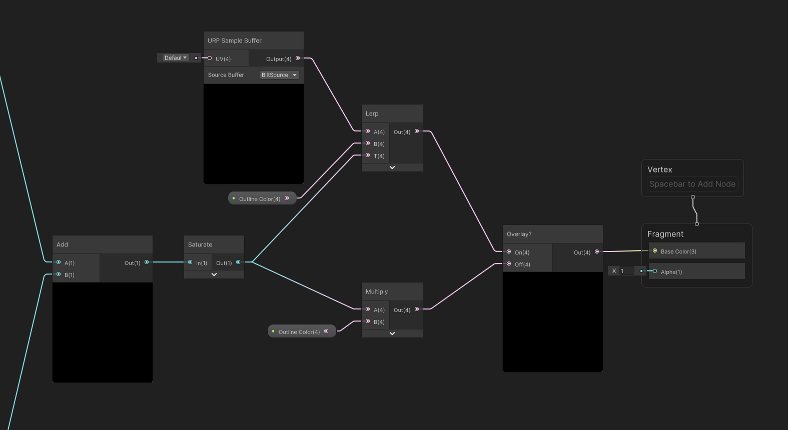
I’ll add two more properties: Outline Color should be self-explanatory, while Overlay is a Boolean Keyword; if it is on, then we’ll display the outlines over the original image, and if it’s off, we’ll display only the outlines.
When Overlay is turned on, we’ll take a URP Sample Buffer in BlitSource mode and use a Lerp node to pick between that (the A slot) and the Outline Color (the B slot), using the Saturate value as the interpolation factor (the T slot). When Overlay is turned off, just multiply the Saturate result by Outline Color. Finally, output the keyword node directly to the Base Color block on the output stack, and that’s the graph complete!
There’s just a little more work that needs to go into displaying the effect.
Displaying the Effect
In the Project View, create a material using the shader we just wrote and pick whatever parameters you want. Then, find your project’s Renderer Data asset - a new URP project should include them in Assets/Settings. My project uses the one called URP-HighFidelity-Renderer, a name which just rolls off the tongue. Select it, and at the bottom, click the Add Renderer Feature button and choose Full Screen Pass Renderer Feature. It’s a long and silly name but bear with me.
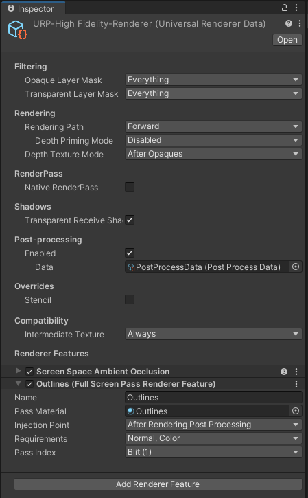
This Renderer Feature instructs URP to run whatever material we choose on the screen; by default, it uses one which inverts the screen colors - I suppose it’s at least obvious when it’s active! Name the feature something like “Outlines”, the drag the material we created onto the material field. We can keep the Injection Point as After Rendering Post Processing, but make sure that in the Requirements, both Color and Normal are selected, as this option controls which data is passed to our shader. Finally, set the Pass Index to Blit and our outline effect should be visible in both the Scene View and Game View!

If you end up using this effect in a game, I’d love to see it!
Conclusion
I have very good impressions of the Fullscreen Shader Graph after my first use. It’s a lot easier to use than code-based Renderer Features, although I would be interested in making a tutorial for those too, as I don’t think Fullscreen Shader Graph would be suitable for all effects (and it’s not available in 2021 LTS, which many of you are likely still using). I don’t think there’s a way to integrate these graphs with URP’s volume system either, which is a shame (maybe there is and I missed it though).
If you’re in the market for more post-processing effects, check out my own Snapshot Shaders Pro. Also on sale for the rest of March on itch.io!
Acknowledgements
Special thanks to my Patreon backers for February - March 2023!
JP kai Jack Dixon Morrie Mr.FoxQC Phillip Baxley Josh Swanson Moishi Rand Alexis Lessard Mikel Bulnes Ming Lei Muhammad Azman Olly J Paul Froggatt Will Poillion Zachary Alstadt 源 刘