Halftone is a technique used in printing to simulate the appearance of a color gradient by using a pattern of differently-sized dots. The technique can be extended to use offset layers of different colors, such as cyan, magenta, and yellow, to mimic a full-color gradient. In this tutorial, I’ll show you how to create a shader that takes the diffuse light contribution from the main light and converts the shaded regions into a dot pattern of darkened pixels. If any of the screenshots in the article look strange, the effect will probably look best at native resolution on your own computer. Although this tutorial is designed for URP Shader Graph, it may be possible to tweak it to work in other pipelines.
For this tutorial, we are using Unity 2021.3.0f1 (LTS) and Shader Graph/URP 12.1.6.

Check out this tutorial over on YouTube too!
Analysis
The halftone effect works by taking the shaded portions of the object and applying colored dots to those parts to darken the albedo color slightly. That means our first task is to find those shaded regions. I’ll keep this simple, so I’ll only use the diffuse light contribution from the main directional light in the scene.
There isn’t a Shader Graph node to retrieve this information in the latest LTS version of Unity, so we’ll need to use a bit of custom shader code. This project is on GitHub, so you’ll be able to download the code instead of typing it all out if you want.
Once we’ve used this custom code to identify the shaded regions of the object, we’ll turn them into circles, using the lighting amount as a threshold to determine how large the dots are at each point. Let’s start by getting the lighting amount.
The GetMainLight Subgraph
The latest LTS version of Unity doesn’t yet have a node to get this information, so we’ll use a Custom Function node to inject our own shader code, then wrap it in a subgraph so it can easily be reused in other graphs. I’ve used this same code a few times before, such as in my cel shading effect, so this process might be familiar to you!
You’ll need to create a new file called Lighting.hlsl. This must be done outside of the Unity Editor, because there is no built-in preset to create an HLSL file. Or, you can just lift the file directly from GitHub.
void MainLight_float(float3 WorldPos, out float3 Direction, out float3 Color,
	out float DistanceAtten, out float ShadowAtten)
{
#ifdef SHADERGRAPH_PREVIEW
    Direction = normalize(float3(0.5f, 0.5f, 0.25f));
    Color = float3(1.0f, 1.0f, 1.0f);
    DistanceAtten = 1.0f;
    ShadowAtten = 1.0f;
#else

#if SHADOWS_SCREEN
	half4 clipPos = TransformWorldToHClip(WorldPos);
	half4 shadowCoord = ComputeScreenPos(clipPos);
#else
	half4 shadowCoord = TransformWorldToShadowCoord(WorldPos);
#endif

    Light mainLight = GetMainLight(shadowCoord);

    Direction = mainLight.direction;
    Color = mainLight.color;
    DistanceAtten = mainLight.distanceAttenuation;
    ShadowAtten = mainLight.shadowAttenuation;
#endif
}
I won’t go over each line with a fine-toothed comb, but let’s discuss what this code is broadly doing.
-
The code contains one function named
MainLight_float. It uses floating-point precision, hence the_float. -
The world-space position is the only input to the function.
-
We output the direction, color, and attenuation of the light. There are two attenuation values, which each represent the strength of the light between 0 and 1 (after factoring in distance and shadows respectively).
-
The bottom half of the code (from
#if SHADOWS_SCREENonwards) is used to calculate these values. -
That code fails to run in Shader Graph preview windows, because they do not contain ‘real’ lights. Instead, we use fake default values to simulate a light.
-
I’ve only tested this code in URP, but there might be ways to tweak it for HDRP or the built-in render pipeline. Yes, the built-in pipeline supports Shader Graph now!
Here’s an interesting theoretical debate: are any lights in computer graphics real? On one hand, no, but on the other hand, they do brighten your monitor slightly…
Next, we’ll create a subgraph via Create -> Shader Graph -> Sub Graph. In the middle, we’ll add a Custom Function node, and in its Node Settings, make these changes:
-
Set the Type to File.
-
Drag the Lighting.hlsl file into the Source slot.
-
Type
MainLightinto the Name slot. This the same name we gave the function inside Lighting.hlsl, but without the_floatbit at the end.
In previous Unity versions, the option to create the graph might be under Create -> Shader -> Sub Graph.
Once you’ve done that, set up the inputs and outputs to be the same as those we used in the Lighting.hlsl code. Just make sure the names and types are correct!

On the property blackboard, we’ll add a Vector3 called WorldPos, which will be the sole input to the subgraph.

When you click the Output node, which is already on the graph surface, we can add the same outputs as we used on the Custom Function node, except we’ll only include one attenuation value because we can easily combine them on the graph surface.
On the graph surface, connect the WorldPos property to the Custom Function node, and multiply the two attenuation values before outputting everything.

It’s tedious to go through this process each time you want to use lighting information, so I’m glad there is a Get Main Light Direction node coming in Unity 2022.1 - I hope they add more lighting nodes in the future. However, I try to stick to the latest LTS version, so instead we have to suffer.
With the GetMainLight subgraph out of the way, we can move on to the main graph.
The Halftone Graph
We’ll start by creating a new Unlit graph via Create -> Shader Graph -> URP -> Unlit Graph, which I’ll name “Halftone”. You might be asking, “shouldn’t we use a Lit graph instead since we’ll be using lighting in the shader?” That’s a good question! However, the Lit graph just sticks on lighting and shading at the end and doesn’t let you configure how the lighting gets applied, so instead we use an Unlit graph, where no lighting is automatically applied, and manually calculate it.
On previous versions of Unity, the Unlit graph option can be found at Create -> Shader -> Universal Render Pipeline -> Unlit Shader Graph.
The Halftone Properties
Double-click the Halftone graph and the Shader Graph editor will appear. We’ll start by adding the following properties to the graph:
-
The
Base ColorandBase Textureproperties exist on most of my shaders, and we use them to control the base color, or albedo, of the object. -
The
Shading Multiplieris aFloatproperty which I’ll use to control how much darker the shadowed regions of the object are than the lit regions. The default value will be 0.1. -
The
Circle Densityproperty, anotherFloat, is used to control the size of the dots in the halftone effect. When you increase it, the size of each dot decreases. The default value will be 5, but you’ll most likely want to increase it on materials which use this shader. -
The
Softnessproperty is aFloatwhich controls how much blending there is on the edge of a halftone dot. I’ll make the default value 0, but we can increase it if we want. -
Rotation, anotherFloatproperty, is used to rotate the grid of dots so they’re not necessarily aligned to the X-Y plane in screen space. -
The
Lit Threshold, aFloat, determines the cutoff point where we treat lighting values as shaded or not; when we cross below this threshold, we start drawing dots. We’ll make it 1 by default, but you can tweak it to look however you want. -
The
Falloff Threshold, yet anotherFloat, is used to control how large the region is where we use dots. Think of it as a way to make shadows appear further across the object. If we increase it, then the dots won’t extend as far through the shaded region. I’ll make the default value 2.5. -
Finally, we’ll add a
Booleankeyword calledUse Screen Space. When active, as is the default, we’ll sample the halftone dots in screen space. When unticked, we’ll use UV space instead, which means the dots become aligned to the object geometry instead. Results in this mode may vary greatly depending on how the UVs are set up for your particular mesh!

That’s the properties done. There are many of them, but each one has a purpose and can be used to customize the effect heavily. Next, we’ll start adding nodes to the graph surface.
The Halftone Graph Surface
To start, we’ll sample the Base Texture property using a Sample Texture 2D node, then multiply the result by the Base Color property. This gives us a color to use for all fully-lit areas of the object.

For the parts of the object which are in the shade (i.e., the parts that will be covered in halftone dots), we’ll take the lit color and use a Colorspace Conversion node to switch from an RGB (red-green-blue) color to an HSV (hue-saturation-value) color. This is just a different way to represent colors, which happens to also be a Vector3. We can separate out each component with a Split node, leave the hue and saturation alone, then multiply the value (or lightness, the third component of the vector) by the Shading Multiplier property. We can link back each component into a new Vector3, convert back from HSV to RGB using a second Colorspace Conversion node, and we now have a color for bits of the object in the shade.

These two colors are the values we’ll pick between for the graph output, so we’ll add a Lerp node and connect the base albedo to the A slot and the darkened albedo to the B slot. The third parameter, T, which is the interpolation factor between 0 and 1, will require a bit more effort to calculate. For now, just connect the Lerp output to the Base Color block on the master stack.

Leave plenty of space to the left of the Lerp node and we’ll start figuring out how to apply the halftone dot pattern. We’ll start with working out some UVs.
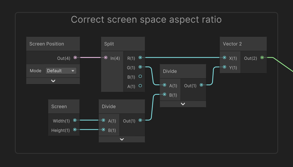
If we want to use screen space to display the halftone dots, we use a Screen Position node. The UVs start at (0, 0) in one corner and end at (1, 1) at the other corner, but the screen is rectangular. That means if we use these UVs, then the dots will appear stretched horizontally, so we’ll take the aspect ratio of the screen into account. Here’s how we can do that:
-
Divide the screen width by the screen height. Both these values are available from the
Screennode. -
Divide the screen space y-coordinate by that value.
-
Link back the unmodified x-coordinate and the modified y-coordinate into a new
Vector2.

If we instead don’t want to use screen space, we can just use a UV node to align the UVs to the object, no modifications needed. To pick between screen space and tangent space UVs, drag the Use Screen Space keyword onto the graph and connect the two UV values accordingly. This gives us a base set up UV coordinates to work with.

Multiply these UVs by the Circle Density property then use a Rotate node to apply the Rotation property (I will continue using Radians on the Rotate node, but you can swap to Degrees if you want). This gives us a final set of UVs before we create the halftone dot pattern.

So, how will we create the pattern? There are several ways to do this, and most tutorials will recommend using a texture. For this shader, I’ll be using the Voronoi node. That might be surprising, since we typically use Voronoi patterns for things like marble surfaces, or Wind Waker’s water which is kind of Voronoi-like. However, if you set the Angle Offset of a Voronoi node to zero, then you get the following:
-
The output values form a neat grid aligned to whatever UVs you used as input.
-
The values in the grid are all between 0 and 1.
-
Each value represents the distance of the pixel from the center of its grid tile.
-
Using a
Stepnode on these values results in a neat grid of tiny circles. That’s what we want!

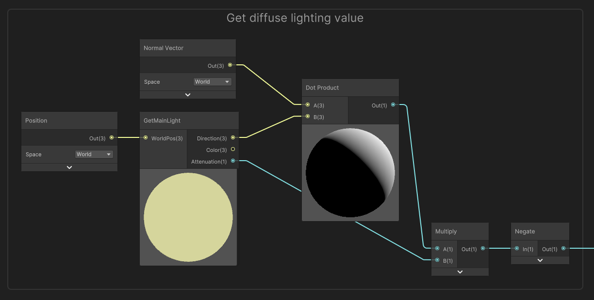
We’ll come back to this in a second, so don’t add a Step node just yet. Next, we need to calculate the amount of light falling on the object. I’ll use a simplified model and just calculate the diffuse lighting contribution from the main light. To do that, we take the Dot Product between the Normal Vector on the surface of the object and the light direction, the latter of which we can get with our GetMainLight subgraph.
The resulting values are between -1 and 1, so I’ll multiply by the attenuation value (which is itself between 0 and 1), then use a Negate node to invert the result. That last node might seem strange, but it makes a later step work better.

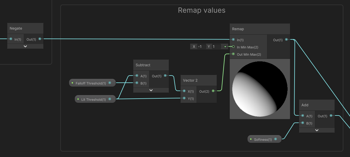
We now have light values between -1 and 1, but I want to remap them into a nicer range and incorporate the two threshold properties we included. We can do that all in one fell swoop, so here’s what I’ll do:
-
Feed the lighting amount into a
Remapnode. -
Set the In Min Max values to -1 and 1 respectively.
-
The Out Max value should be equal to the
Lit Thresholdproperty. -
The Out Min value should be equal to
Lit Thresholdminus theFalloff Threshold.

There are just a couple of nodes left to tie everything together. Go back to the Voronoi node from earlier and drag out a Smoothstep node from its Out output. The Smoothstep function is very much like the Step function, except there is some blending of values that lie between the two thresholds of Smoothstep, whereas Step uses a single threshold.
For the first threshold, just use the output from the Remap node directly. For the second threshold, we’ll take the Remap node output and add the Softness property to it. If you’ve used appropriate default values for each property, then you should see the halftone effect start to take shape on the preview of the Smoothstep node.

Finally, we can connect the output of the Smoothstep node to the third parameter of the Lerp node we originally added, and the graph is complete!

Below, you’ll see the completed shader once more. It’s up to you how you use it - you might think it works best on completely untextured objects like the sphere in front, or you could try experimenting a bit with texturing, like on the Triceratops model in the back. I’d recommend not making the textures too busy, though, or the halftone dots might start to look a bit crowded.

In most cases, screen space mode will do what you want. However, you can still get interesting results if you use tangent space sampling instead. It’s not really “true halftone”, I don’t think, but you can play around with this and find a look that works for you!

Conclusion
The halftone effect can be used in conjunction with other stylized toon effects if you’re working on a comic book style game, and it’ll look right at home.
If you’re making a stylized toon game, then I think this shader on the Asset Store might work for you:
Acknowledgements
Supporters
Support me on Patreon or buy me a coffee on Ko-fi for PDF versions of each article and to access certain articles early! Some tiers also get early access to my YouTube videos or even copies of my asset packs!
Special thanks to my Patreon backers for July 2022!
Jack Dixon Morrie Pisit Praiwattana Underwater SUN 川东 唐
FonzoUA Josh Swanson Moishi Rand
Alexis Lessard Brocktoon Harshad JP kai Mikel Bulnes Ming Lei Muhammad Azman nicolo Olly J Paul Froggatt Will Poillion Ying Mo Zachary Alstadt