Shader Graph is a tool for creating shaders in a visual way - without code. Unity provides the most common and useful operations in the form of nodes, which we can place on a graph and connect together to make more complex behaviour, and in this tutorial, we’ll learn how Shader Graph works and how you can create your very first shader! I’m using Shader Graph 7.3.1, so this tutorial may not be fully accurate for later versions of Shader Graph, but many of the concepts will be the same.
Unity Basics aims to teach you a little part of Unity in an easy-to-understand and clear format.
This tutorial is aimed at people who have never used Shader Graph before, but ideally you have a bit of experience with the Unity Editor.
Also check out this tutorial on my YouTube channel if reading isn’t your thing:
Installing Shader Graph
Shader Graph is not installed in every project by default. It’s not available at all on the built-in render pipeline, so you will need to make sure you are using URP, HDRP or your own custom SRP. There are multiple ways of installing it.
We can start a new URP or HDRP project using the Unity Hub. When we create a new project in the Hub, you will have the option of selecting a preset; if we choose High Definition RP or Universal Render Pipeline, then Shader Graph will be installed in your project automatically. Personally, I prefer to use URP.
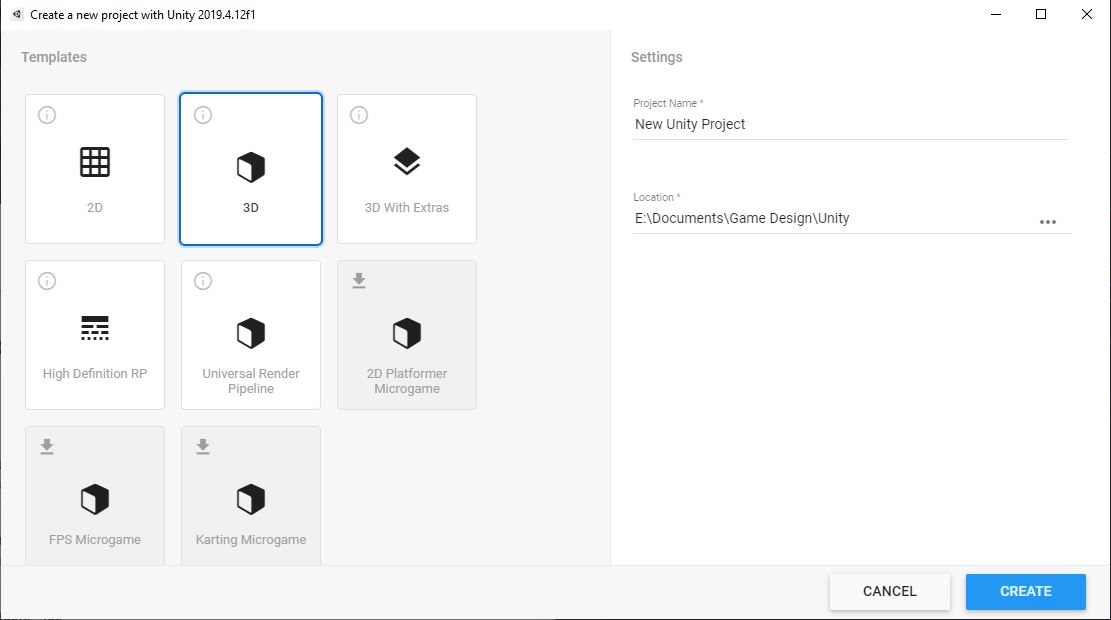 Pick the URP or HDRP preset to install Shader Graph automatically.
Alternatively, you can take a project that already uses the built-in pipeline and upgrade it to URP/HDRP through the Package Manager. You can find it in the toolbar through Window -> Package Manager, then search for “Universal RP” or “High Definition RP” to install one of them. You’ll also need to search for “Shader Graph and install that! If you’re writing your own Scriptable Render Pipeline, you also need to install Shader Graph here, but you’re probably way smarter than me anyway.
The Shader Graph Editor
To create a new shader, right-click in the Project window and go to Create -> Shader, and you’ll be met with a range of options.
 There are several types of shader to pick from.
The top section is full of shader code options, so we’ll ignore those. Then, from top to bottom, we can pick a 2D Renderer graph - the sub-menu gives us Sprite Lit and Sprite Unlit options, but we’ll work with 3D for our graphs. The next is an Unlit Graph, which doesn’t apply any of Unity’s built-in lighting to the object, then a PBR Graph which does; PBR stands for Physically Based Rendering. Next is a VFX Shader Graph, which can be used to integrate with the VFX Graph system, but that’s out of the scope of this tutorial. Finally, a Sub Graph is a handy tool for bundling a node tree together into a single node that can be included in other graphs, much like a method/function in programming, but that’s something we will cover in a later tutorial.
Firstly, we will pick Unlit Graph and name it “UnlitTest” to demonstrate my inability to name things interestingly. Double-left-clicking the Shader Graph icon will open up UnlitTest in the Shader Graph window.
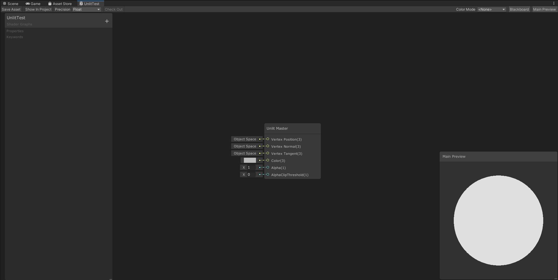 An empty Unlit Graph.
If you’ve never used Shader Graph before, then there’s a lot to take in. Starting with the thin toolbar at the top of the window from left to right, we have:
The Save Asset button. Changes you make to your shader won’t be applied to any materials until you press this, so click it often (or use Ctrl-S).
The Show In Project button. This will open the Project window and select the corresponding shader file.
The Precision drop-down. Usually you won’t need to change this, but shaders can use half- or full-precision for its variables.
On the right-hand-side, the Color Mode can be used to add a color indicator to each node on the graph, but I usually don’t use this.
The Blackboard toggle will turn the list of properties on the left-hand side on or off.
And finally, the Main Preview toggle will enable or disable the Main Preview mini-window in the bottom-right corner.
That’s the basic editor layout - now it’s time to start making our own shaders. We start off with the Unlit Master node already on the graph. Every shader graph will have one of these nodes, and each input into the node - or pin, as they’re also known - correspond to one of the shader’s outputs (although it’s worth noting that this works a little differently in later versions of Shader Graph, but I’m sticking with the LTS version of Unity for now). For example, if I were to click the tiny color box next to the Color pin and change it to red, then the output of the shader will turn red.
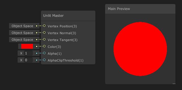 We can change the inputs to these pins directly.
We can also use the output of other nodes to feed these pins. To create your own nodes, right-click anywhere in the empty space on the graph and select Create Node, then use the menus or type the desired node into the search bar. The one we’ll add is called Color, and we can just type “Color” into the bar or find it under Input -> Basic -> Color. This gives us a node with a pin on the right-hand-side labelled “Out”, a box we can click to change the color, and a Mode dropdown. Leave the Mode as Default, then change the color to whatever you want, and when you’re done, left-click-drag from the Out pin onto the Color pin on the Unlit Master node.
 Color nodes let us create new colors to use. There are other nodes like this.
This seems to work well! However, when we create a material that uses this shader, its color will always be yellow. If we want to modify the color on a per-material basis, we need to use a property. On the left-hand-side, you’ll see an empty list of properties - click the plus button to bring up a menu, and select Color.
 Using this drop-down, we can add properties or keywords.
The property we’ve just added has a lot of things we can modify. To start off, we can change the name of the property by double-clicking the rounded tab next to the drop-down arrow - this is a human-readable name, so let’s call it “Base Color”. The Exposed checkbox lets us choose whether this property is visible in the material Inspector, so we’ll leave it ticked. Then there is a Reference field, which is the name we use to refer to this property in scripts (as it’s also the name Unity will use for this property when it autogenerates shader code based on this graph). We can leave it as-is, but you’ll usually see me change these anyway - the convention is usually an underscore, followed by the name, like _BaseColor.
Next up, we have the Default field, which is where we set the default value of the property. Let’s set this to blue. After that, the Mode - as it was on the Color node - determines whether the color uses HDR or not. HDR stands for High Dynamic Range, which lets us set the color to higher-intensity values, but we don’t need to do that so we’ll leave it as Default. Next is the Precision option, which lets us override the graph-wise Precision option, so let’s just set it to Inherit to automatically use the global value. Finally, there’s the Hybrid Instanced checkbox. I have no idea what this does so I’ve never ticked it.
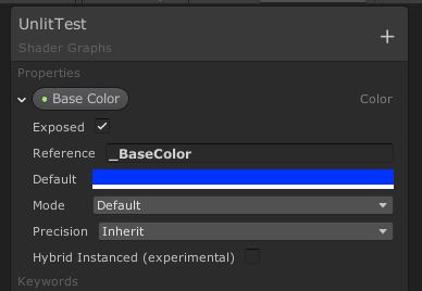 Properties have loads of different, well, properties.
Now that we have a property, we can place it on the graph by selecting the property in the properties window and left-click-drag it onto the graph area. We’ll remove the existing Color node by left-clicking it and pressing Delete, then connect Base Color’s pin to Color on Unlit Master. Remember to save your shader to preserve these changes!
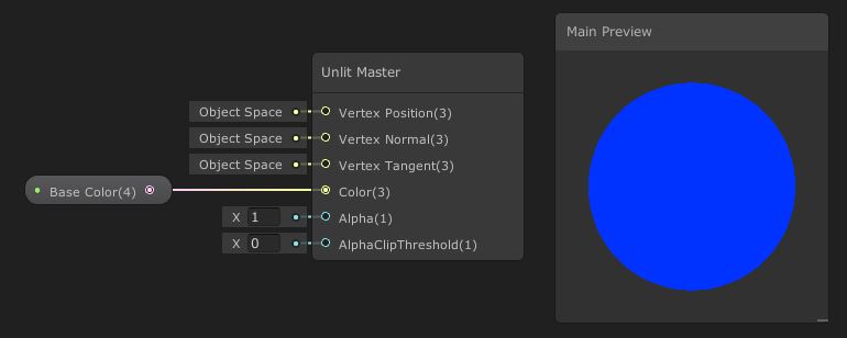 Now our shader output can be customised in the Inspector.
Once we’re back in Scene View, we can create a material, apply the shader to it, and tweak the color in any way we want. Here’s a sphere with the material applied after changing the color to green:
 Now our shader output can be customised in the Inspector.
PBR Graphs
Let’s make a second graph using one of the other master nodes. Go to Create -> Shader -> PBR Graph and name it “PBRTest”. Now, the PBR Master node comes with a few extra pins than the Unlit Master node did.
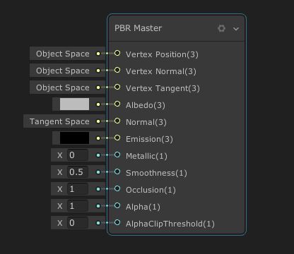 Different master nodes have different input pins.
The Normal pin is for faking details on the mesh by modifying the way lighting interacts on the surface, which obviously doesn’t happen on an unlit material. Emission is for giving objects a bright glow to make them appear as if they’re emitting their own light. Metallic and Smoothness are both for modifying how lighting interacts on the surface - very metallic objects look shiny, and very smooth objects have bright specular highlights. We won’t worry about Occlusion. Alpha is how transparent the object is, and the Alpha Clip Threshold can be used to completely switch off pixels whose alpha is below the threshold.
However, by default, the alpha will not change the transparency, because the material is rendered in opaque mode. Select the PBR Master node and click the tiny cog in the top-right corner to bring up a handful of extra options.
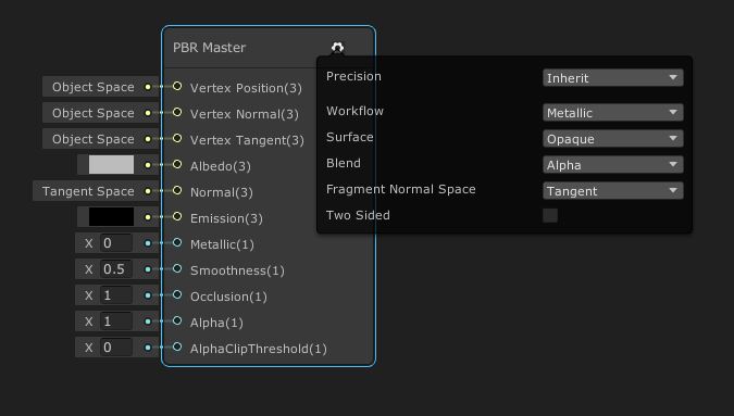 The cog menu contains a few extra options for this shader.
We’re most interested in the Surface option, which we can change to Transparent to start rendering this object with alpha-blended transparency. Transparent rendering is slightly more computationally expensive than opaque rendering, but it shouldn’t be so obvious that it slows your game down.
For this shader, we’re going to read color data from a texture. Add a new property - this time, we’ll add a Texture2D. I’m going to name mine “Main Texture”, then give it a reference value of _MainTexture, which is a special reference, because C# scripts can access this very easily through material.mainTexture rather than needing to use material.GetTexture("_MainTexture"). I’ll leave the other defaults as they are.
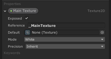 Adding texture properties is as easy as adding color properties.
To read the texture, we’ll need to add a node called Sample Texture 2D to the graph. This one is substantially more complicated than the Color node we added previously. On the left-hand-side inputs, the Texture pin is where we input the texture we want to read, so go ahead and drag the Main Texture property onto the graph and connect it. The UV pin allows us to change what UV coordinates we use to map between the texture space and the model’s vertices - if we leave it as the default UV0, then Unity will use whatever UVs are supplied by the model. The Sampler, which is short for Sampler State, defines how to read the texture - by default, Sample Texture 2D will use the import settings on the texture, but we can override those here.
Add a new Sampler State property in the properties window to see how they work. We can modify the Filter, which determines if and how adjacent pixels are smoothed; the Wrap, which defines what happens if you attempt to sample outside the texture’s dimensions; and, as with other properties, the Precision. This type of property can’t be Exposed, so think of it as a texture sampling setting override for all materials that use this shader. Set whatever values you want, then drag it on the graph and plug it into the Sampler pin.
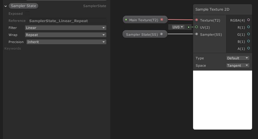 The powerful Sample Texture 2D node together with Sampler State lets us read textures in all kinds of ways.
The Sample Texture 2D node also has options at the bottom. With the Type, we can switch between sampling the texture regularly, or sampling it as if it were a normal map. Leave it as Default. We can also change the Space used to sample the texture, but leave it as Tangent.
Now we come to the outputs on the right. It seems as if there are a lot of them, but in reality, we have the full RGBA color output, plus all four components individually output. We’re going to drag the four-component RGBA output into the Albedo pin on PBR Master. The Albedo pin actually takes in only three components, but that’s not a problem - Unity will silently drop the alpha component. Also connect the singular A output to the Alpha pin on PBR Master - it’s up to you to decide if you want to use transparent rendering or set an alpha cutoff, though. Remember to save your shader!
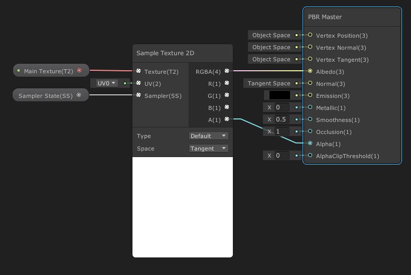 This shader reads a texture and uses that for the albedo color of the object.
Back in the Scene View, I’ve created a material using this shader and used one of the textures that come with the URP/HDRP default scene, a cork-board texture, and applied that to a couple of shapes to see how it gets applied. On these models, you can see that lighting has automatically been applied to them.
 The UV mapping on the cube is better, but the texture has successfully been applied to both objects.
Conclusion
Shader Graph is often seen as a “friendlier” way of getting into shaders than code, not least because there’s less finicky boilerplate to get used to. That’s not to say that Shader Graph is free of weird concepts to get your head around! We’ve seen how to use some of the cornerstone concepts of Shader Graph to build two simple shaders, and from now on it’s up to you to experiment with more of the nodes provided by Shader Graph to make your own effects.
Shader Graph will return in future Unity Basics tutorials, and when it does, I’d like to write a tutorial about the thought process I have when I’m looking at effects and reverse engineering them.
Acknowledgements
Supporters
Support me on Patreon or buy me a coffee on Ko-fi for PDF versions of each article and to access certain articles early! Some tiers also get early access to my YouTube videos or even copies of my asset packs!
Special thanks to my Patreon backers for January 2021!
Gemma Louise Ilett
JP
Jack Dixon Tuomas Männistö
Chris Sims FonzoUA Jesper Kuutti MR MD HARDING Maya Nedeljkovich Moishi Rand Shaun Wall
Anna Voronova James Poole Christopher Pereira sadizeng Zachary Alstadt
And a shout-out to my top Ko-fi supporters!
Hung Hoang Arthur H Megan Taylor Takuya “Somebody”