This tutorial explores one of the simplest lighting models used in 3D rendering - diffuse lighting, also known as Lambertian lighting. In this model, lighting incident on a point on some surface is based solely on the angle between the light source and the normal vector at that point.
Diffuse Lighting
Diffuse lighting is the basis of most photorealistic lighting models. While more advanced models introduce other types of lighting on top of diffuse lighting, such as specular highlighting and rim/fresnel lighting, we’ll need to implement diffuse lighting first. As we discussed in Part 0, diffuse lighting is based on the angle between the viewer and the normal vector of a point on a surface. The viewing angle has no bearing on the lighting on the object - that’s what specular and fresnel lighting are all about.

We’ll look at multiple ways of passing light data to a shader. The more common way of interacting with Unity’s lighting system is by using surface shaders, which are specific to Unity and handle the boilerplate code involved with lighting interactions for us. Surface shaders will be auto-compiled into several functions for each possible combination of rendering path, which is helpful if we want our shaders to “just work”.
If we’re willing to do the maths from scratch, we can also use fragment shaders as usual. This is a lot more portable to other platforms, so if you’re looking into using these tutorials in an OpenGL/glsl project, then this is the path you’ll want to take.
Surface shaders
We create a surface shader in a similar way as creating an image effect in the previous Super Mario Odyssey shader series. In the Project pane, right-click and select Create -> Shader -> Standard Surface Shader. Or, if you’ve downloaded the tutorial project from GitHub - the link is at the top of the page - all the template shaders will be created for you.

Name this shader DiffuseSurf, or if you’re using the tutorial project, it’s available in Shaders/DiffuseSurf.shader. We’re greeted by a basic shader - replace the template code with the following:
Shader "CelShading/DiffuseSurf"
{
    Properties
    {
        _MainTex ("Albedo (RGB)", 2D) = "white" {}
    }

    SubShader
    {
        Tags { "RenderType"="Opaque" }

        CGPROGRAM
        #pragma surface surf Standard

        struct Input
        {
            float2 uv_MainTex;
        };

        void surf (Input IN, inout SurfaceOutputStandard o)
        {
            o.Albedo = 1.0;
        }

        ENDCG
    }

    FallBack "Diffuse"
}
Let’s go over the parts of the shader in order. It’s named CelShading/DiffuseSurf, so it’ll appear in Unity’s shader dropdown under CelShading -> DiffuseSurf. The Properties block is empty, and we have a FallBack defined - the hardware will pick Unity’s built-in Diffuse shader (different to this one!) if the one we’re writing is unsupported. The SubShader has the usual Tags, but the interesting part starts with #pragma surface surf Standard; this is similar to the process we used to define which functions were our vertex and fragment shaders, so we’re telling Unity our surface shader is called surf, plus there’s an added Standard parameter that tells Unity we’re using the built-in physically-based lighting model. We can use Lambert or BlinnPhong as alternatives to Standard if we don’t want physically based lighting.
The surface shader takes in data encapsulated in an Input struct, and outputs data in a SurfaceOutputStandard struct (or a SurfaceOutput struct when a non-PBR lighting model is used - the Physically-Based-Rendering pipeline was introduced in Unity 5). The Input struct in this example has a single member variable - uv_MainTex. Detailed information on the input structure for surface shaders can be found here; for the uv_MainTex variable, all you need to know is that we can pass texture coordinates to the surface shader by writing uv followed by the texture name (in this case, _MainTex). Inside the shader, we define properties of the surface rather than calculate the lighting ourselves - in this simple example, we’re setting the base albedo colour to white.
Also supplied in the tutorial project are materials with each of the shaders attached. Attach the Materials/DiffuseSurf material to objects in the example scene, and they’ll turn white, with plastic-looking shading. That’s diffuse lighting in action!
Adding Material Properties
Now let’s add some more flexibility to our shader. Right now, everything is defined in the shader and all variables being passed between Unity and the GPU are being passed behind the scenes. We want to be able to modify material parameters in the Inspector.
Let’s add some Properties. It’s common to have a base albedo colour for the material, which we’ve hard-coded in our shader as full-white. Instead, we’ll pass this as a property. Additionally, we’ll want to apply a texture to the material, so we’ll also pass in _MainTex as we have before.
Properties
{
    _MainTex ("Albedo (RGB)", 2D) = "white" {}
    _Color ("Tint Color", Color) = (1,1,1,1)
}

// Before Input struct definition.
sampler2D _MainTex;
fixed4 _Color;
Instead of hard-coding the albedo colour, we’ll use these properties. If we don’t modify them in the material’s Inspector, we won’t see any changes - but we’ll have the flexibility to easily change them. The surf function now looks like this:
void surf (Input IN, inout SurfaceOutputStandard o)
{
    fixed4 c = tex2D (_MainTex, IN.uv_MainTex) * _Color;
    o.Albedo = c.rgb;
}
We use the same tex2D function as before, using the UV coordinates we passed in the Input struct. That struct acts in a very similar way to the appdata and v2f structs we’ve seen in past tutorials, although we’re only passing one piece of data to the surface shader in this example. The texture sample is multiplied by the base colour property we named _Color, and the result of that multiplication is used as the material’s output albedo colour.
By moving this logic outside of the shader code, we can create multiple materials with the same behaviour, but different input parameters. Experiment with them and see what results you get.
A few notes on Surface shaders
You may have noticed that the surf() function has two variables passed in - the Input struct that we defined ourselves, and another struct called SurfaceOutputStandard. The latter is defined as an inout variable, meaning that it’s passed into the function as a parameter, but it’s also output to the next stage of the graphics pipeline. SurfaceOutputStandard is used for much more than just setting the albedo colour; it’s used for defining every property about a surface that the standard lighting model utilises.
// From https://docs.unity3d.com/Manual/SL-SurfaceShaders.html:
struct SurfaceOutputStandard
{
    fixed3 Albedo;      // base (diffuse or specular) color
    fixed3 Normal;      // tangent space normal, if written
    half3 Emission;
    half Metallic;      // 0=non-metal, 1=metal
    half Smoothness;    // 0=rough, 1=smooth
    half Occlusion;     // occlusion (default 1)
    fixed Alpha;        // alpha for transparencies
};
We’ll be exploring some of these in other tutorials. I just thought it was worth noting where the struct comes from - after all, it’s passed into the surf function seemingly from nowhere!
Fragment shaders and lighting
Surface shaders automate much of the lighting interaction for us, but it’s also possible to specify this behaviour using a good ol’ fragment shader. We’ll make things easy on ourselves and only consider one directional light, but it’s possible to consider multiple lights, including point lights and spotlights.
Let’s refresh ourselves on vertex and fragment shaders. We’ll start this one off by passing in _MainTex and _Color as we did in the Surface shader section and output a base albedo colour/texture using those properties.
Properties
{
    _MainTex ("Texture", 2D) = "white" {}
    _Color ("Albedo color", Color) = (1, 1, 1, 1)
}

...

sampler2D _MainTex;
float4 _MainTex_ST;
float4 _Color;

...

fixed4 frag (v2f i) : SV_Target
{
    fixed4 col = tex2D(_MainTex, i.uv) * _Color;
    return col;
}
We must define structs to pass data between shader pipeline stages. We’ll pass an appdata struct to the vertex shader, which will transform vertices and UV coordinates into the correct formats, then pass the transformed data to the fragment shader in the v2f struct.
struct appdata
{
    float4 vertex : POSITION;
    float2 uv : TEXCOORD0;
};

struct v2f
{
    float2 uv : TEXCOORD0;
    float4 vertex : SV_POSITION;
};

...

v2f vert (appdata v)
{
    v2f o;
    o.vertex = UnityObjectToClipPos(v.vertex);
    o.uv = TRANSFORM_TEX(v.uv, _MainTex);
    return o;
}
Putting it all together, this shader outputs an unlit object. Try applying a material with this shader to the objects in the test scene. Now let’s apply some diffuse lighting.
We’re going to use the angle between the light source and the normal vector on the object to determine the lighting amount. However, the amount of lighting is not quite linear with the angle - instead, we’ll use the ‘dot product’ between those two vectors to calculate the lighting amount. If you’re not familiar with what the dot product is, we take the sum of the products of corresponding values in two vectors, with the caveat that the dot product only works with unit vectors, so we’ll normalise them both first. It’s also called the ‘scalar product’ because the result is a single value, rather than another vector. Here’s an example, where x and y are unit vectors:
The dot product is equal to zero when two vectors are perpendicular, and equal to one when they are parallel. Plus, it does not change linearly with a linearly changing angle - it’s great for modelling lighting falloff. It’s just the cosine of the angle multiplied by the magnitude of both vectors - you can see from the cos that the result is not linear with the angle. To use it, we’ll first need to pass lighting data and normals to the shader.
We will modify the Tags in order to pass lighting data. We’ll tell Unity that we want to pass lighting data, then instruct it to send over only data about directional lights, as we’re not interested in other types of light in this example.
Tags
{
    "RenderType" = "Opaque"
    "LightMode"  = "ForwardBase"
    "PassFlags"  = "OnlyDirectional"
}
With these parameters, Unity will allow our shader to use lighting data. The LightMode is set to ForwardBase because we wish to use the forward rendering path in Unity, and the PassFlags are set to OnlyDirectional, we’re telling Unity we don’t want to send over any data apart from the directional light data. More information is found here. We’ll have access to the directional light’s direction - that’s all we’ll need to calculate the amount of light it contributes to an object’s surface.
We shall also pass over the normals of the object. Normals are passed per-vertex and interpolated between vertices the same way that vertex colours would be when processing them in the fragment shader - but we need to process them before reaching the fragment shader anyway! We’ll pass the normals inside appdata to our vertex shader using the NORMAL semantic.
float3 normal : NORMAL;
A normal is defined per-vertex in Unity object space, so we’re going to need to convert it to world space. Since object space doesn’t take into account the rotation of the object in the world - which is rather important when it comes to the vector calculations we’ll need shortly - we will use the UnityObjectToWorldNormal function to transform the normal vector from appdata into the appropriate format. We’ll also need to modify v2f to make sure it carries the new world normal over to the fragment shader - we’ll add a worldNormal variable with the NORMAL semantic.
struct v2f
{
    float2 uv : TEXCOORD0;
    float4 vertex : SV_POSITION;
    float3 worldNormal : NORMAL;
};

v2f vert (appdata v)
{
    v2f o;
    o.vertex = UnityObjectToClipPos(v.vertex);
    o.uv = TRANSFORM_TEX(v.uv, _MainTex);
    o.worldNormal = UnityObjectToWorldNormal(v.normal);
    return o;
}
We now have access to the normals and the directional light in the fragment shader - so let’s use them.
fixed4 frag (v2f i) : SV_Target
{
    fixed4 albedo = tex2D(_MainTex, i.uv) * _Color;

    float3 normal = normalize(i.worldNormal);
    float diffuse = dot(_WorldSpaceLightPos0, normal);

    fixed4 col = albedo * diffuse;
    return col;
}
Let’s deconstruct this. I’ve introduced the albedo variable to combine the input texture and base colour. The normal variable denotes the normal vector - the only thing we need to take care of is to normalise the vector (make its magnitude equal to 1) so that the dot product operates correctly. It’s super convenient that there’s a built-in normalize function for this purpose - similarly, there’s a built-in dot function that performs the dot product.
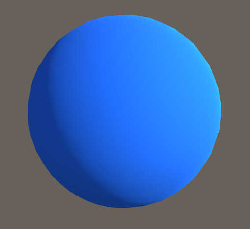
The _WorldSpaceLightPos0 variable is one of those passed in with the lighting information - it’s the direction of our directional light, despite “Pos” being in the name. Remember that only the direction of the light matters so our shader doesn’t consider its position at all. The diffuse variable denotes the proportion of the directional light falling on this fragment - and we multiply it by the albedo colour in order to get our final pixel colour. Running the shader now gives us a shadow on all our objects! However, it’s a bit dark and isn’t affected by changing the colour of the light, so we’ll add a little more to the shader.
Let’s use the colour properties of the light, as well as the ambient colour of the scene. For the former, we’re going to include another file called Lighting.cginc underneath the UnityCG.cginc inclusion.
#include "Lighting.cginc"
This will give us access to a few more shader variables that aren’t included automatically. There’s a list of shader variables that lists all included shader variables (although the same list mentions you must include the Lighting.cginc for some of them). We’ll use the _LightColor0 variable from that file to retrieve the colour of our directional light - which can be changed inside the Inspector - and the unity_AmbientSky variable that’s included by default and denotes the colour of the top part of the skybox texture. If we were doing this perfectly, we would find some way of taking unity_AmbientEquator and unity_AmbientGround into account too, but this is just a demonstration. All we need to do is tweak our final colour calculation.
fixed4 col = albedo * (diffuse * _LightColor0 + unity_AmbientSky);
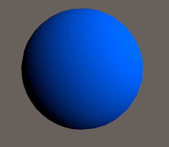
With that, our shader is complete. If you change the directional light colour to black, the object will still be lit according to its albedo (texture + base colour) and the ambient light from the skybox, and the object responds to changes in the hue of the light, too. This implementation of a diffuse shader works just as well as the one created using a surface shader!
Conclusion
Today we’ve seen how we can use a surface shader in conjunction with Unity’s lighting engine to obtain some simple diffuse shading on our models. We saw how we can interact with Unity’s lighting data manually inside vertex and fragment shaders and we used the vertex normals together with a directional light to recreate the same diffuse effect as the surface shader. In the next tutorial, we’ll expand upon this and replace the smooth lighting gradient with a set number of discrete steps to mimic a cartoon aesthetic - this forms the crux of our cel shaded effect.